Apparatus and method for managing fluids in a fuel cell stack

a technology of apparatus and fuel cell, applied in the field of electrochemical systems, can solve the problems of fuel starvation, ice formation before, ice blockage, etc., and achieve the effects of fuel starvation, uneven flow sharing, and fuel starvation

Inactive Publication Date: 2008-05-15
BDF IP HLDG
View PDF9 Cites 29 Cited by
  • Summary
  • Abstract
  • Description
  • Claims
  • Application Information

AI Technical Summary

Benefits of technology

[0022]According to yet another embodiment, a method for managing fluids in a fuel cell stack to prevent liquid collection and ice formation, comprises providing at least one body having a porous medium adjacent a flow field plate of at least one fuel cell of the fuel cell stack between a reactant manifold opening and a reactant flow field channel of the flow field plate to allow passage of at least one of a fuel and an oxygen-containing gas therethrough, and block from passage therethrough, a flow of liquids.

Problems solved by technology

Such water accumulation can also lead to ice formation before and during freeze startups.
This water freezes under appropriate environmental conditions, resulting in ice blockage.
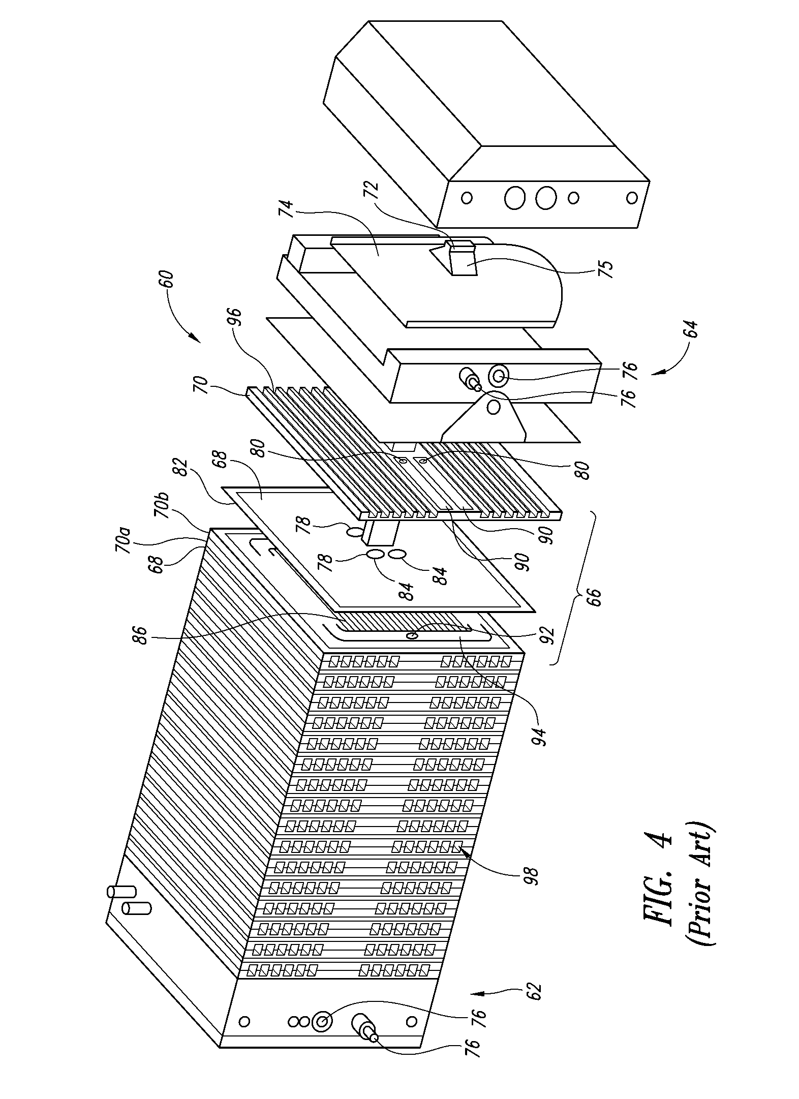
These blockages typically prevent efficient reactant access and flow to the flow field channels 86 and may cause uneven flow sharing and fuel starvation in the fuel cell system 60.
In addition to purging the water from the system 60, other methods of mitigating ice blockages include operating the fuel cell system 60 extremely dry; however, even then, some ice blockage occurs because it is nearly impossible to completely prevent water from exiting the fuel cells 66.
Furthermore, operating fuel cell systems in extremely dry conditions typically impedes performance and reduces the fatigue life of the system 60.

Method used


Image

  • Apparatus and method for managing fluids in a fuel cell stack
  • Apparatus and method for managing fluids in a fuel cell stack
  • Apparatus and method for managing fluids in a fuel cell stack

Examples


Embodiment Construction

[0036]Reference throughout this specification to “one embodiment” or “an embodiment” means that a particular feature, structure or characteristic described in connection with the embodiment is included in at least one embodiment. Thus, the appearances of the phrases “in one embodiment” or “in an embodiment” in various places throughout this specification are not necessarily all referring to the same embodiment. Furthermore, the particular features, structures, or characteristics may be combined in any suitable manner in one or more embodiments.

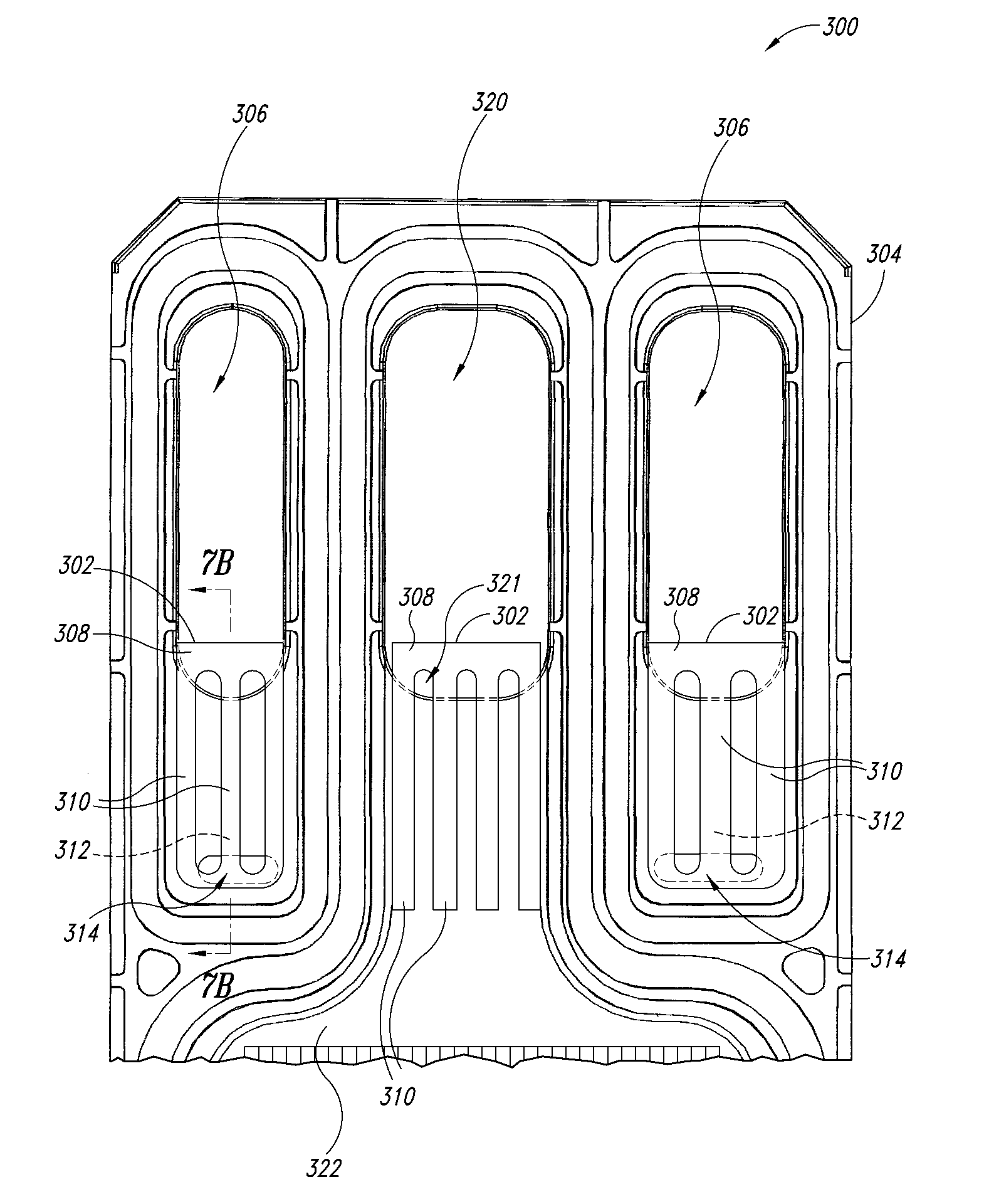
[0037]FIG. 6 illustrates one embodiment of the present invention, in which a fuel cell stack 200 comprises a body 201 having a porous medium 202 interposed between two adjacent flow field plates. One of the flow field plates 204 is depicted in FIG. 6; the other is not shown for clarity of illustration of the porous medium 202. The porous medium 202 comprises a porous material that allows passage of reactant gases, for example a fuel, such as a...


PUM

PropertyMeasurementUnit
thicknessaaaaaaaaaa
hydrophobicaaaaaaaaaa
volumeaaaaaaaaaa

Abstract

A flow field plate assembly for use in a fuel cell, a plurality of which can form a fuel cell stack, comprises first and second flow field plates and a body comprising a porous medium interposed between the first and second flow field plates, the porous medium being operable to allow passage of a fuel and an oxygen-containing gas therethrough, and block from passage therethrough, a flow of liquids to prevent water collection and ice formation, which may block passages formed on at least a portion of the first and/or second flow field plates.

Description

CROSS-REFERENCE TO RELATED APPLICATION[0001]This application claims the benefit under 35 U.S.C. § 119(e) of U.S. Provisional Patent Application No. 60 / 824,803 filed Sep. 7, 2006 where this provisional application is incorporated herein by reference in its entirety.BACKGROUND OF THE INVENTION[0002]1. Field of the Invention[0003]The present invention generally relates to electrochemical systems, and more particularly, to an apparatus and method for managing fluids in a fuel cell stack.[0004]2. Description of the Related Art[0005]Electrochemical fuel cells convert reactants, namely fuel and oxidant fluid streams, to generate electric power and reaction products. Electrochemical fuel cells generally employ an electrolyte disposed between two electrodes, namely a cathode and an anode. An electrocatalyst, disposed at the interfaces between the electrolyte and the electrodes, typically promotes the desired electrochemical reactions at the electrodes. The location of the electrocatalyst gen...

Claims


Application Information

Patent Timeline
Patent Type & Authority Applications(United States)
IPC IPC(8): H01M8/02H01M8/10
CPCH01M8/0258H01M8/0271H01M8/04089Y02E60/50H01M8/04291H01M8/241H01M8/04253H01M8/2483H01M8/0267H01M8/2457
Inventor CHRISTIE, ANDREW LEIGHFARRINGTON, SIMONRICHARDS, CHRISTOPHER J.HAAS, HERWIG R.
Owner BDF IP HLDG
Why Eureka
Try Eureka