Magnet Type Rodless Cylinder

a rodless cylinder, magnet-type technology, applied in the direction of positive displacement liquid engines, pumps, machines/engines, etc., can solve the problems of stick-slip problem, lack of smooth movement of conventional magnet-type rodless cylinders, etc., and achieve the effect of smooth movement of the slide body

Active Publication Date: 2008-05-22
HOWA MASCH LTD +1
View PDF3 Cites 5 Cited by
  • Summary
  • Abstract
  • Description
  • Claims
  • Application Information

AI Technical Summary

Benefits of technology

[0013]In view of the above problem in the prior art, it is an object of the present invention to provide a magnet-type rodless cylinder, which is capable of smoothly moving the slide body in the initial stage of movement.
[0017]That is, in the present invention, in a state where no internal pressure is acting on the pistons accommodated in the plurality of cylinder holes, the pistons which are magnetically coupled to the slide body are deviated in the axial direction of the tubes and are producing a magnetic holding force. Therefore, when the internal pressure is acted upon the pistons, the slide body can be smoothly moved from a halted state.
[0018]The cylinder thrust varies in proportion to the total cross sectional area of the plurality of cylinder holes. Therefore, when the rodless cylinder of a large cylinder thrust is not required, a plurality of cylinder holes having small cross sectional areas may be arranged in parallel. Furthermore, in the present invention, by arranging the cylinder holes close to each other, the height of the slide body can be decreased, and the width of the slide body can be decreased as compared to that of the prior art in which the cylinder holes are not arranged close to each other, when a plurality of cylinder holes are arranged in parallel in the horizontal direction. Therefore, the cylinders as a whole become flat and compact.
[0019]By forming the cylinder tubes as circular cylinder tubes, the movement is smoother, and by joining the outer circumferences of the cylinder tubes, a stable and close arrangement is attained.

Problems solved by technology

Therefore, conventional magnet-type rodless cylinders lack smoothness in the movement due to a stick-slip phenomenon at the start of the slide body 101.
Therefore, the above stick-slip problem occurs.

Method used


Image

  • Magnet Type Rodless Cylinder
  • Magnet Type Rodless Cylinder
  • Magnet Type Rodless Cylinder

Examples


Embodiment Construction

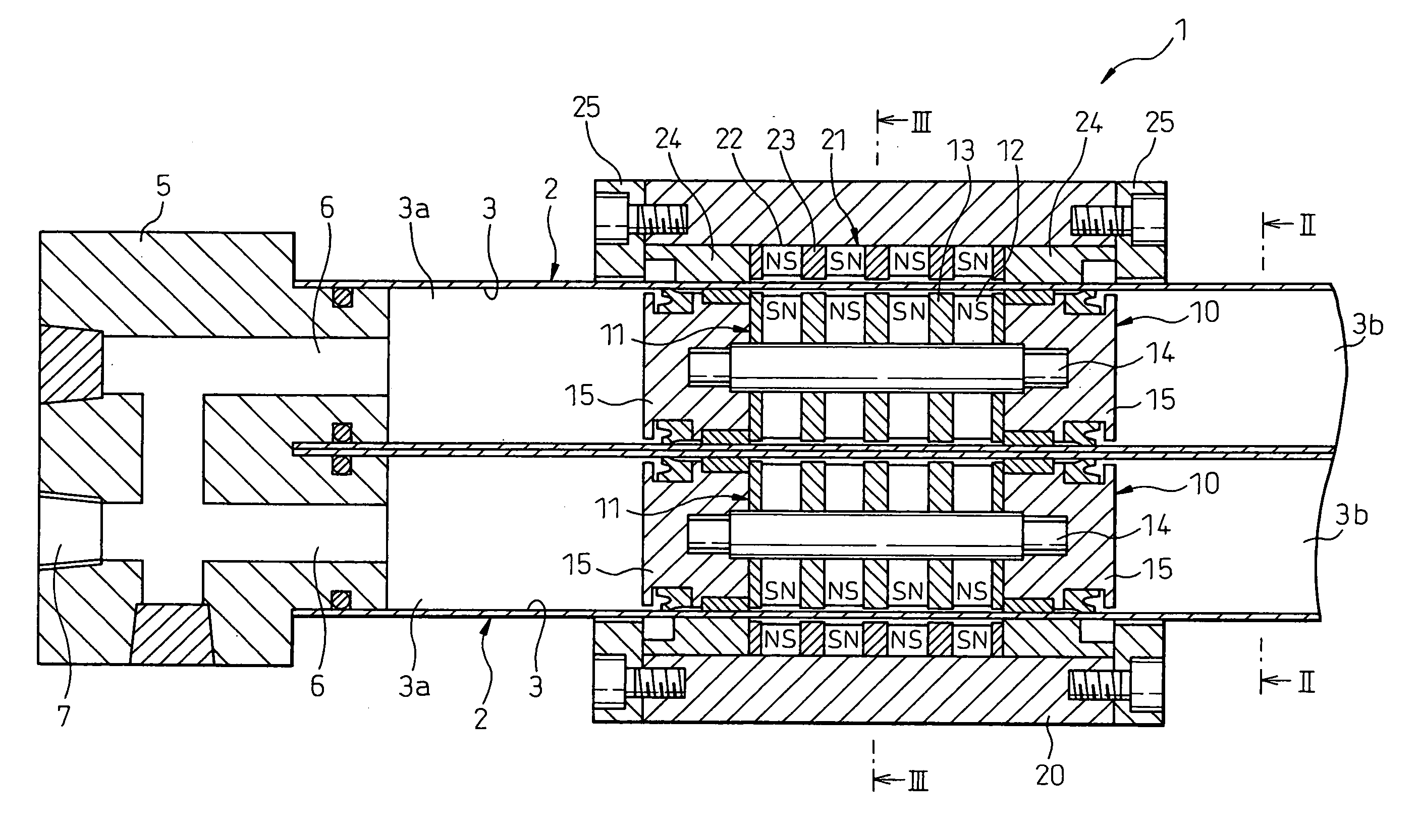
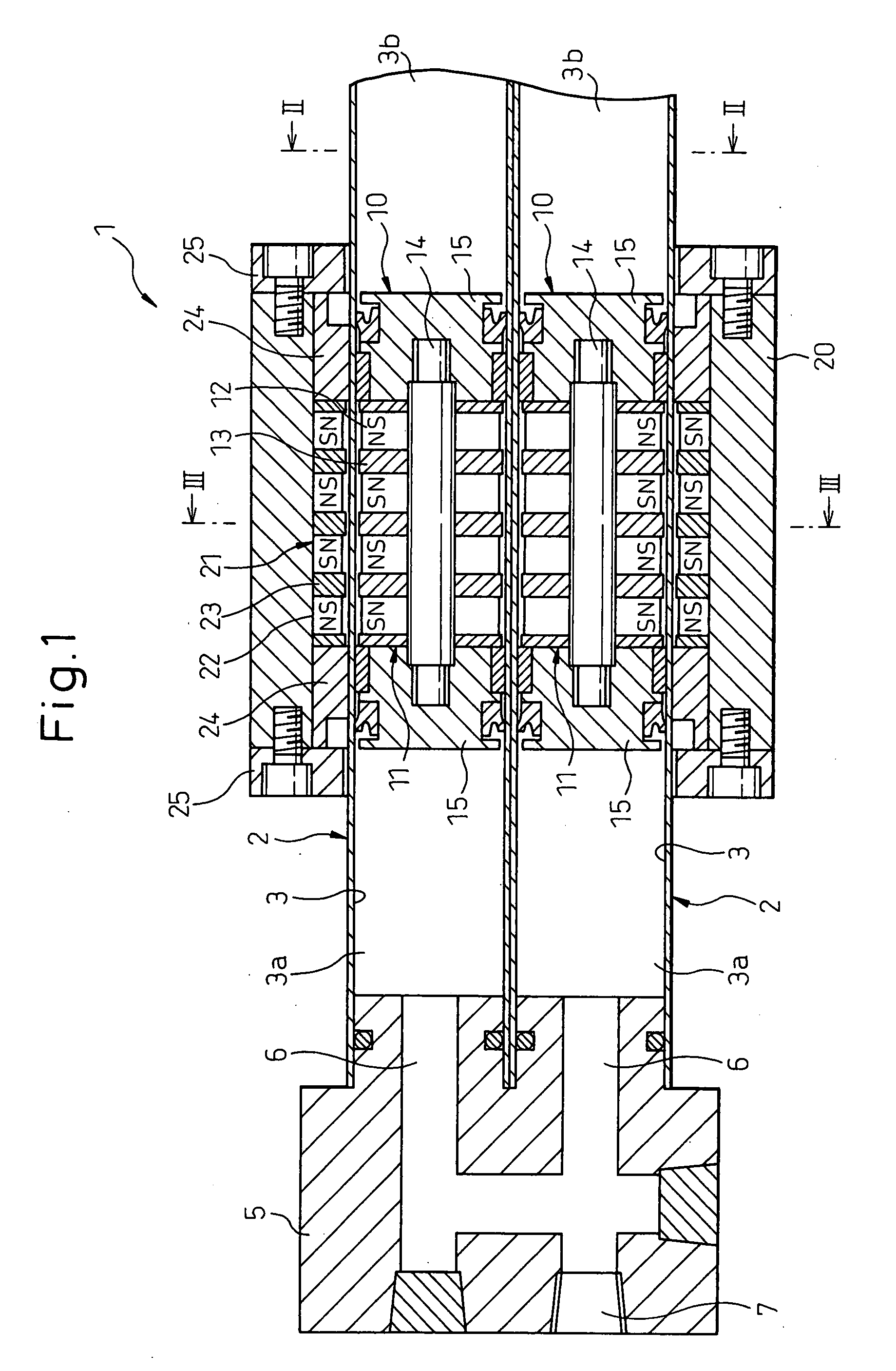
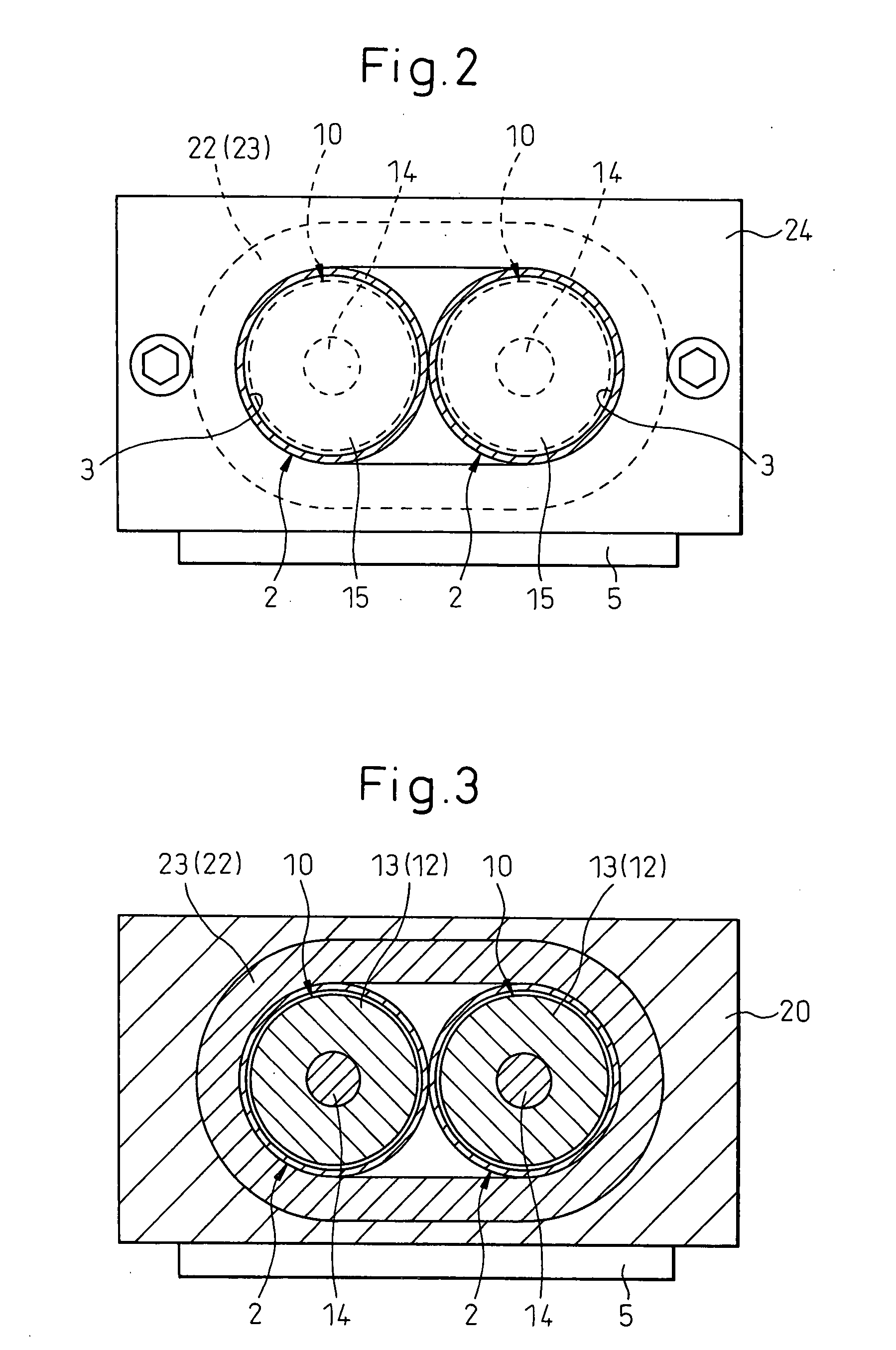
[0031]An embodiment of the magnet-type rodless cylinder of the invention will now be described with reference to FIGS. 1 to 3.

[0032]In FIG. 1, the magnet-type rodless cylinder 1 includes a plurality of (two in this case) cylinder tubes 2. In this embodiment, the cylinder tubes 2 are cylindrical tubes having an exactly circular outer circumferential shape, and include therein cylinder holes 3 of an exactly circular shape in cross section extending in the axial direction of the tubes. The plurality of cylinder tubes 2 are arranged in parallel with portions of their outer circumferential surface being in contact with each other.

[0033]The cylinder thrust varies in proportion to the cross sectional areas of the pistons, i.e., varies in proportion to the cross sectional areas of the cylinder holes 3 of the cylinder tubes 2. Therefore, when the cylinder thrust is set to be the same as that of the conventional magnet-type rodless cylinder employing only one cylinder tube, the cross sectiona...


PUM


Abstract

Repulsive magnetic forces in the axial direction of cylinder tubes act between the rows 11 of inner magnets of pistons 10, 10 accommodated in two cylinder tubes 2, 2, and the inner magnets 12 of the pistons 10 come to a halt being slightly deviated relative to the outer magnets 22 in the axial direction of the tube. Due to this deviation, a magnetic holding force Fc is produced between the inner and outer magnets 12, 22. Since the magnetic holding force Fc is produced in a static state, a smooth movement can be attained from a static state suppressing the occurrence of a stick slip phenomenon at the start of movement as compared to the prior art, which does not produce the magnetic holding force in a static state.

Description

TECHNICAL FIELD[0001]The present invention relates to a magnet-type rodless cylinder in which pistons are magnetically coupled to a slide body on the outer side of a cylinder tube by inner magnets disposed on a plurality of pistons disposed in a plurality of cylinder holes.BACKGROUND ART[0002]In a conventional magnet-type rodless cylinder as is well known, inner magnets are disposed on a piston accommodated in a tube, and outer magnets or magnetic members are provided in a slide body disposed on the outer side of the tube. The piston and the slide body are coupled together by the magnetic coupling force between the inner magnets and the outer magnets or the magnetic members. As the piston is moved in the tube by a fluid supplied to the tube, such as compressed air, the slide body on the outer side of the tube moves following the piston.[0003]In conventional magnet-type rodless cylinders, in general, the slide body moves based on the movement of the piston (i.e., inner magnets), the ...

Claims


Application Information

Patent Timeline
Patent Type & Authority Applications(United States)
IPC IPC(8): F15B15/14F04B35/00
CPCF15B15/1404F15B15/086F15B15/14
Inventor MINOWA, NAOKIYOSHIDA, HIROSHIHORIKAWA, AKIYOSHINODA, MITSUO
Owner HOWA MASCH LTD
Why Eureka
Try Eureka