Electric connection box

a technology of electric connection box and box body, which is applied in the direction of electrical apparatus construction details, electrical apparatus casings/cabinets/drawers, and modifications using gaseous coolants, etc. it can solve the problems of reducing reducing the density and complicating the shape of the inside of the case. , to achieve the effect of improving the radiation performance of the electric connection box and reducing the air density

Inactive Publication Date: 2008-05-22
AUTONETWORKS TECH LTD +2
View PDF0 Cites 15 Cited by
  • Summary
  • Abstract
  • Description
  • Claims
  • Application Information

AI Technical Summary

Benefits of technology

[0009]According to the present invention, the air inflowing into the case from the inlet contacts with the heat generating component arranged inside of the air path, so that the heat produced from the heat generating component is transmitted to the air. Then, the density of the air decreases because of the raised temperature of the air, and thus the chimney effect causes the air climbing up inside of the air path. And then, the outflow of this air from the exhaust outlet enables the heat produced from the heat generating component to be exhausted to the outside of the case. Consequently, the radiation performance of the electric connection box can be improved.

Problems solved by technology

However, in these days, density growth of the electric connection box is required.
High temperature inside of the case might decrease the performance of the electronic component mounted in the circuit board.
This complicates the shape of the inside of the case, thereby disturbing the air flow therein.
It is therefore difficult to sufficiently cool the electronic component.

Method used


Image

  • Electric connection box
  • Electric connection box
  • Electric connection box

Examples


Embodiment Construction

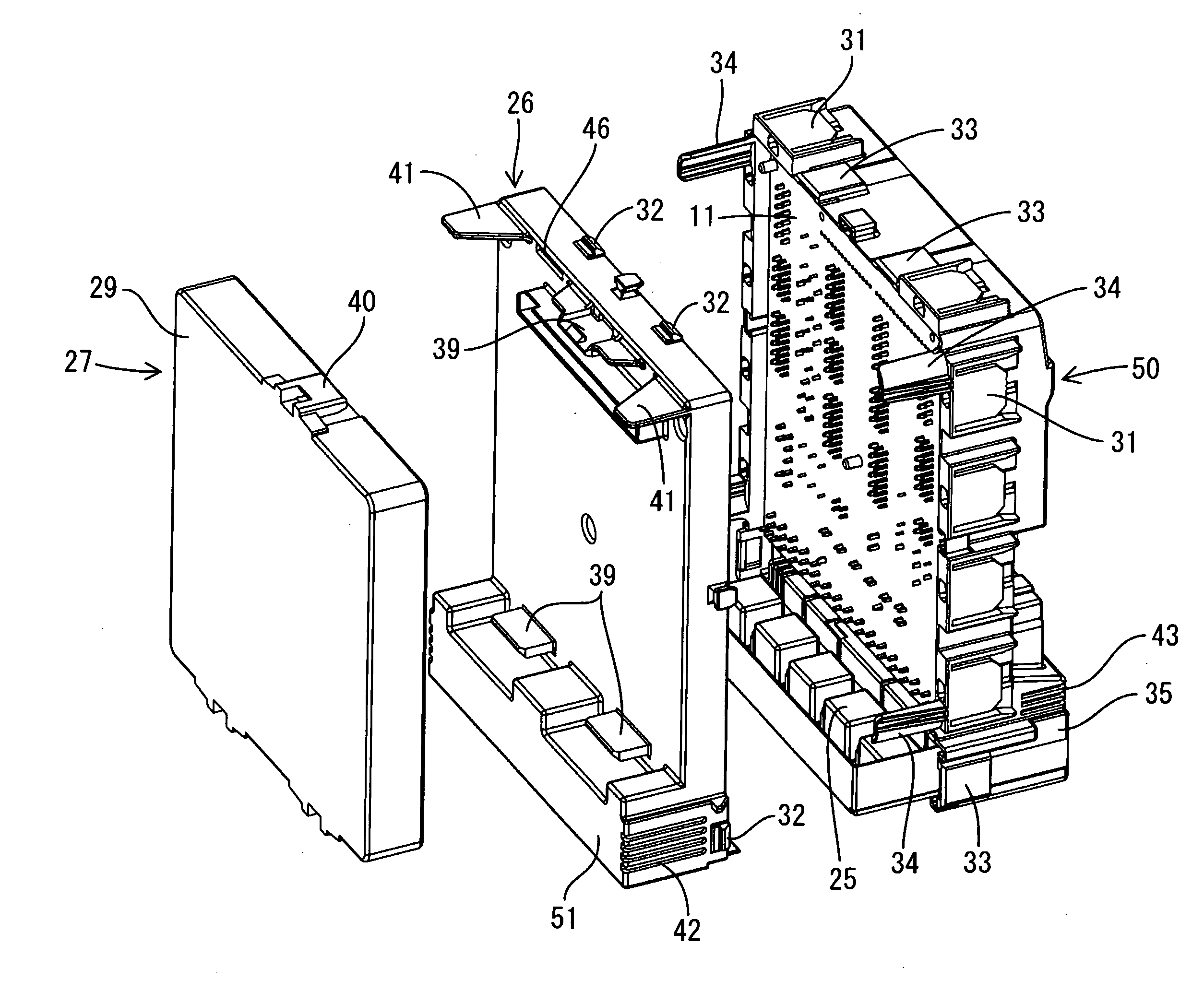
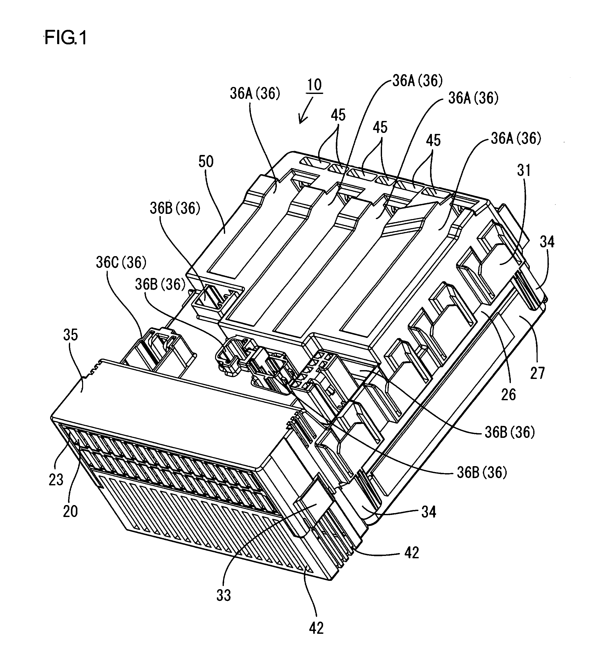
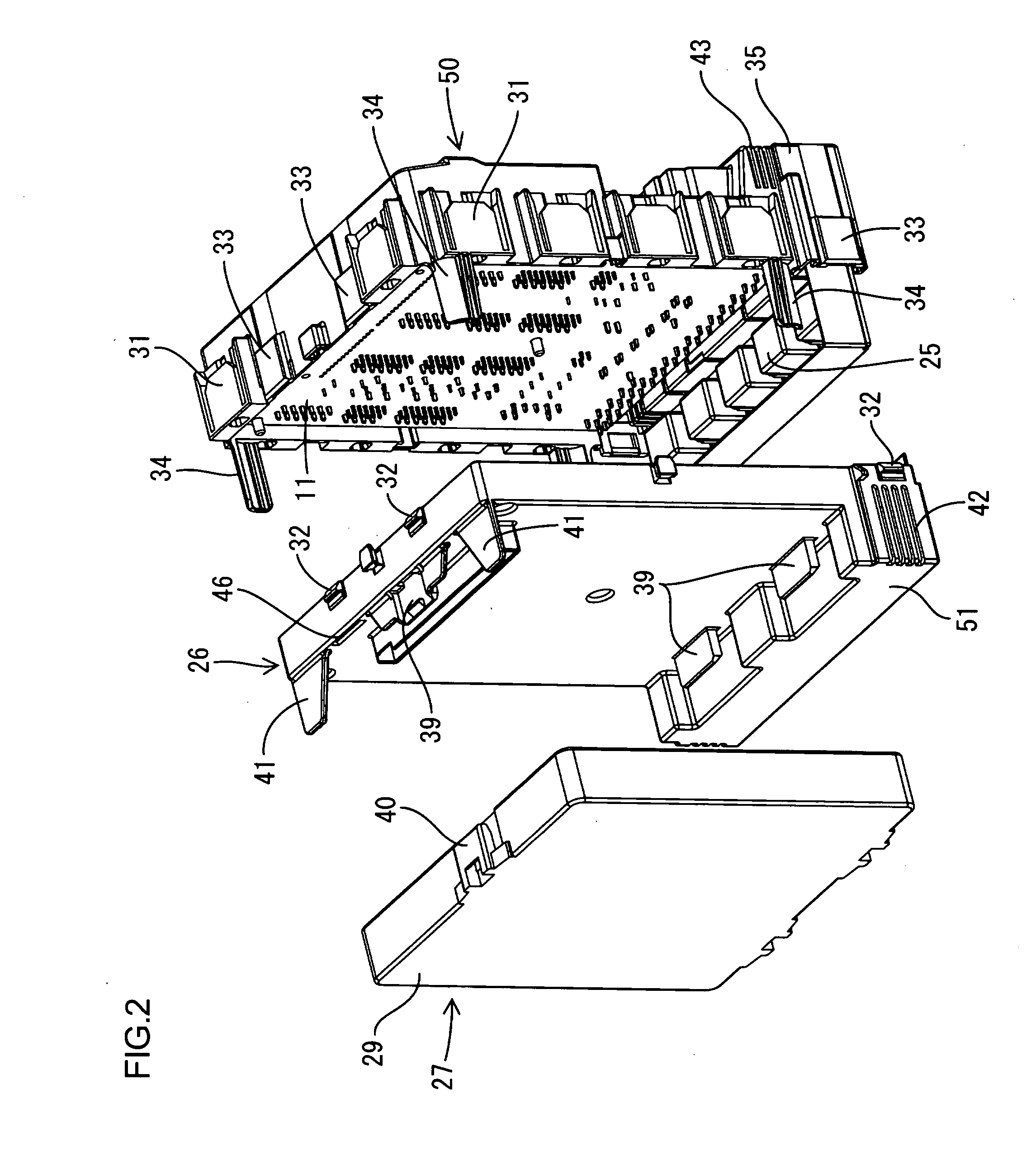
[0019]In the following, one illustrative aspect of the present invention is described in reference to FIGS. 1 to 8. An electric connection box according to the present illustrative aspect is mounted in between a battery (not shown) and a vehicle electrical component such as a lamp or a power window (not shown), and controls energizing of these vehicle electrical components. The electric connection box is mounted inside of a vehicle (not shown) in a longitudinal position as shown in FIG. 6 for use. This electric connection box is comprised of a circuit board 11 housed inside of a flat case 10.

[0020]Circuit Board

[0021]On the both surfaces of the circuit board 11 having a nearly-oblong shape, an electrically-conducting path (not shown) is formed by printed wiring technology. On the right surface of the circuit board 11 in FIG. 7 (hereinafter referred to as ‘mounting surface’ in some cases), an intermittent relay 12 (corresponding to the electronic component in the present invention) is...


PUM


Abstract

One aspect of the present invention can include an electric connection box having a circuit board, a case inside of which said circuit board is housed, a plurality of fitting depressions capable of being fitted with an external electrical component, positioned on a side wall of the case opposing a board surface of the circuit board. Further, an air path inside of said case is defined by the plurality of fitting depressions positioned as an arrayed side by side with a spacing in between, and the air path circulates the air up and down between the plurality of fitting depressions, and an inlet positioned in the case and in communication with the air path, an exhaust outlet is positioned in the case in communication with the air path and positioned above said inlet, and a heat generating component is positioned in the air path.

Description

CROSS REFERENCE TO RELATED APPLICATION[0001]This application claims priority from Japanese Patent Application No. 2006-310652 filed Nov. 16, 2006. The entire content of this priority application is incorporated herein by reference.FIELD OF THE INVENTION[0002]The present invention relates to an electric connection box, comprising a circuit board housed inside of a case.DESCRIPTION OF THE RELATED ART[0003]Literature 1 (Japanese Unexamined Patent Application Publication No. 2001-197628) has been known as a conventional electric connection box. The electric connection box according to Literature 1 houses a circuit board in which an electronic component is mounted inside of a case. The case is composed of a lower case and an upper case to be assembled so as to cap the lower case. In the upper case, a connector housing having a shape protruding in and out of the upper case is formed.[0004]The above-mentioned electronic component produces heat when energized. According to the conventional ...

Claims


Application Information

Patent Timeline
Patent Type & Authority Applications(United States)
IPC IPC(8): H05K1/02
CPCH05K5/0208H05K7/20009H05K7/026
Inventor SHIMIZU, TATSUYAHASHIKURA, MANABUNISHIDA, FUTOSHI
Owner AUTONETWORKS TECH LTD
Why Eureka
Try Eureka