Biometrics-secured transaction card

a biometric and transaction card technology, applied in the field of electronic scanning of transaction cards, can solve the problems of inconvenience for the authorized card bearer, use of conventional magnetic strip cards, and defeat the purpose of pins

Inactive Publication Date: 2008-05-22
THE PROCTER & GAMBLE COMPANY
View PDF3 Cites 37 Cited by
  • Summary
  • Abstract
  • Description
  • Claims
  • Application Information

AI Technical Summary

Benefits of technology

The present invention is a transaction card that uses biometrics to verify the identity of the user before allowing data to be transmitted. The card contains a biometric sensor, a microprocessor, a power source, and a data-release circuit that can enable or disable data transmission. The card also has stored biometric data and transactional data. The biometric sensor on the card sends its data to the microprocessor, which compares it with the stored data. If there is a match, the microprocessor activates the data-release circuit, allowing a card reader to read or receive the transactional data. This technology ensures secure transactions and prevents unauthorized data transmission.

Problems solved by technology

The technical problem addressed in this patent text is the need for a transaction card that offers greater security without requiring a PIN or other extraneous information. The card should be adaptable for both magnetic strip and RF transactions, and should limit fraudulent transactions executed under duress to small monetary amounts.

Method used


Image

  • Biometrics-secured transaction card
  • Biometrics-secured transaction card
  • Biometrics-secured transaction card

Examples


Embodiment Construction

[0020]The present invention will now be described more fully in detail with reference to the accompanying drawings, in which the preferred embodiments of the invention are shown. This invention should not, however, be construed as limited to the embodiments set forth herein; rather, they are provided so that this disclosure will be complete and will fully convey the scope of the invention to those skilled in the art.

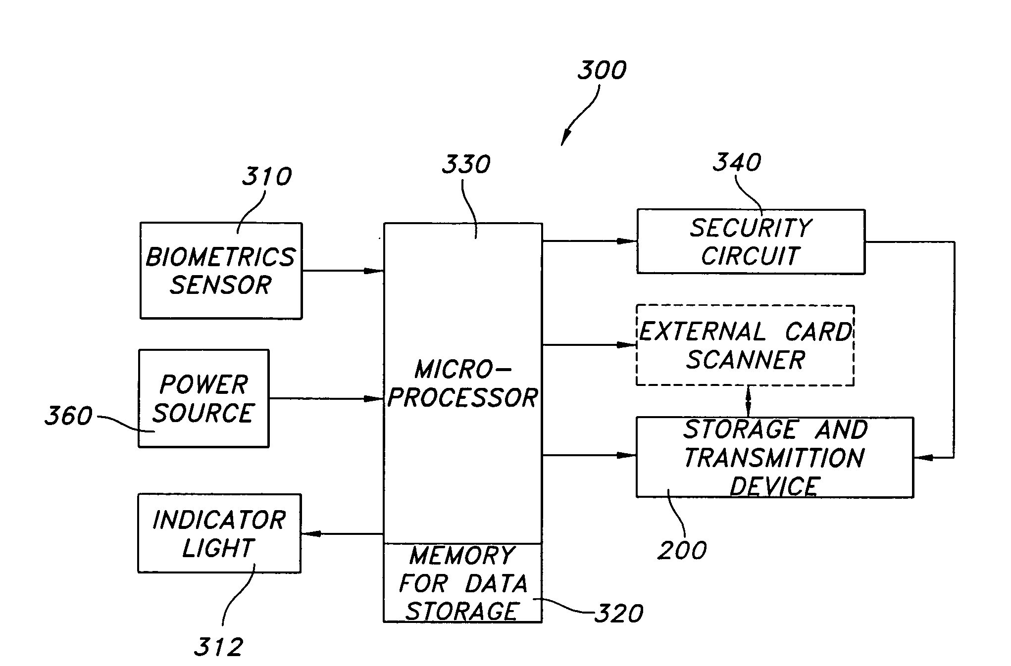
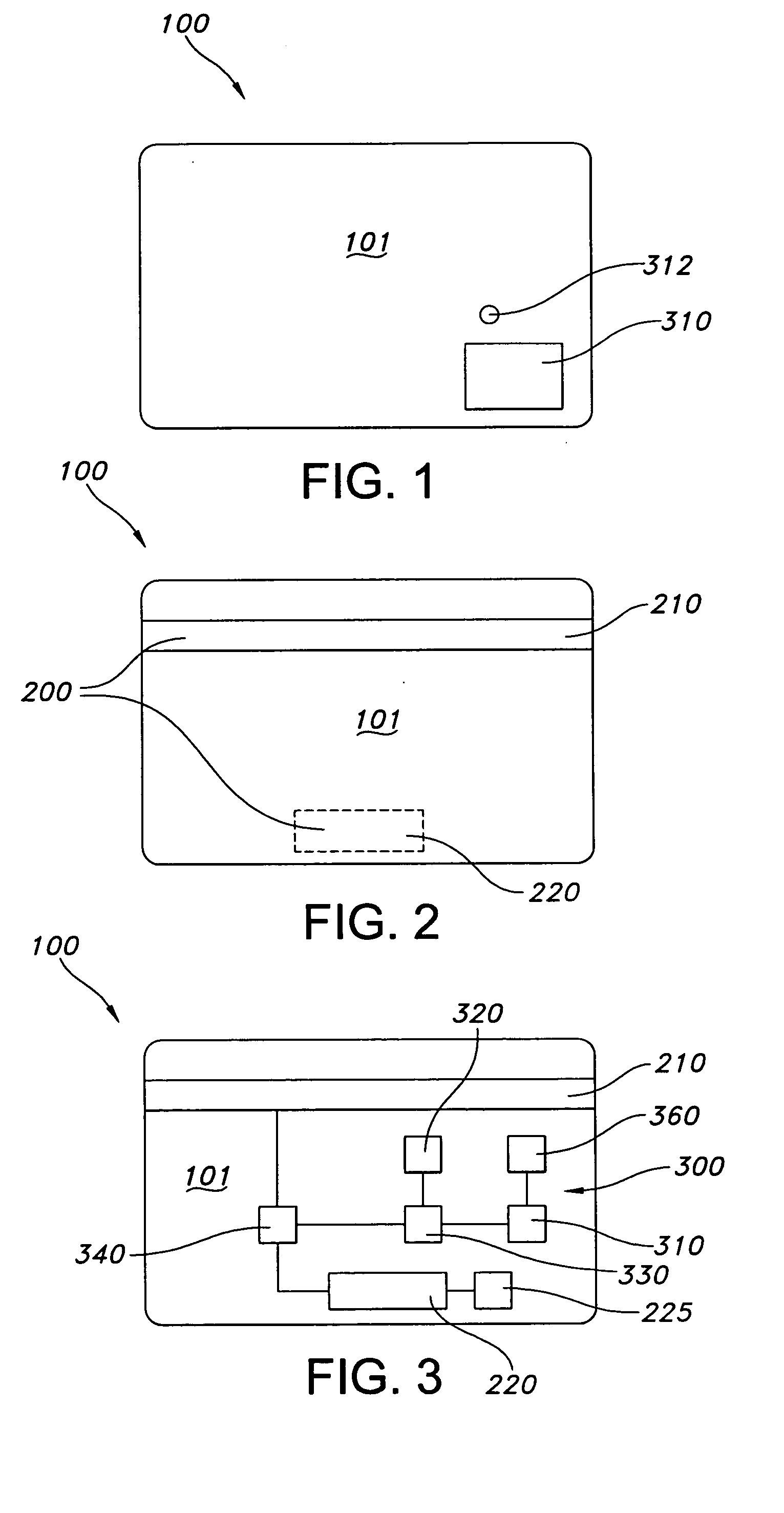
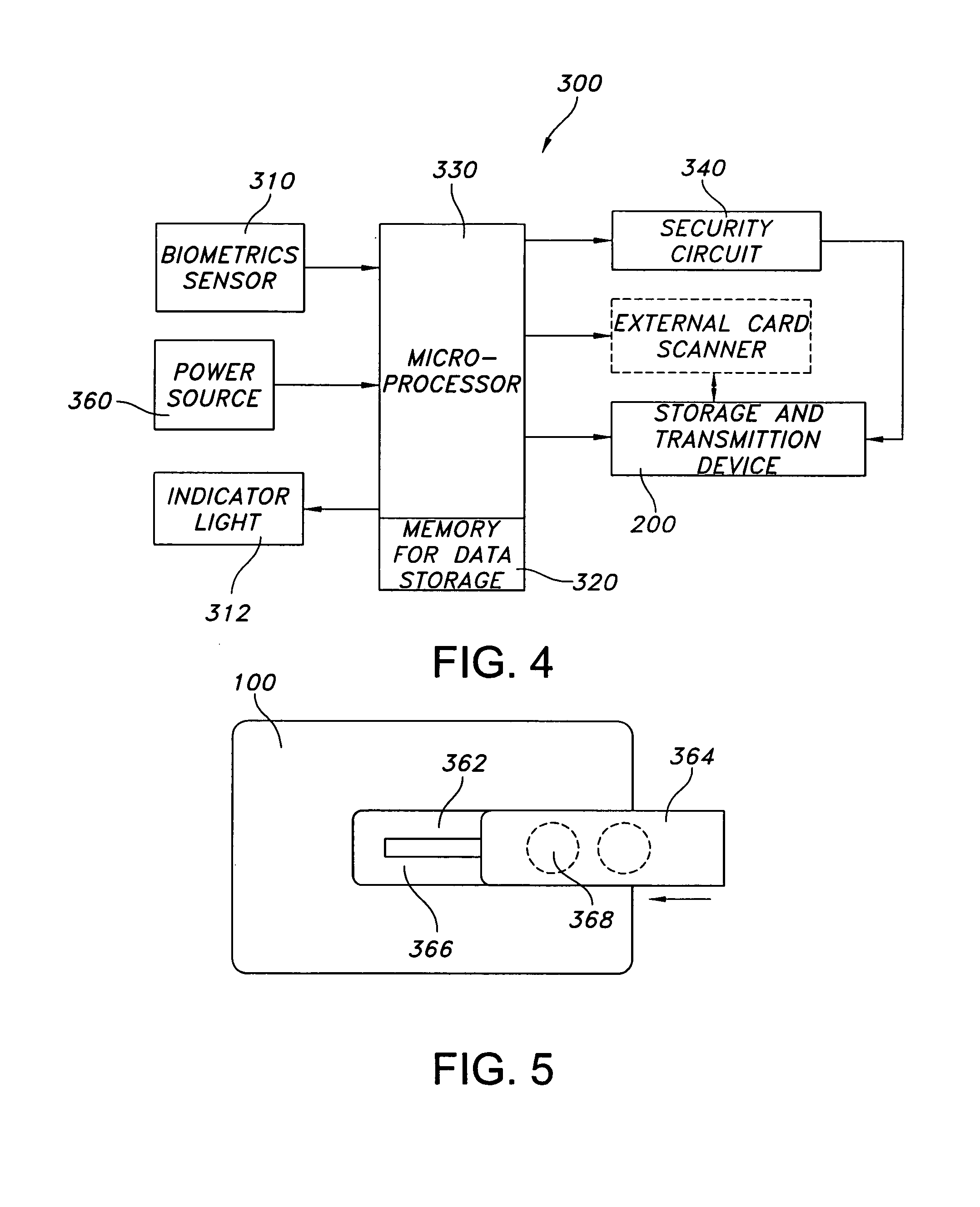
[0021]FIGS. 1 and 2 show the external faces of a biometrics-secured transaction card 100 according to the invention; FIG. 3 shows the various components arranged on the card; FIG. 4 is a block diagram of the components; and FIG. 5 illustrates a removable battery pack that is insertable into the biometrics-secured transaction card 100. FIGS. 1 and 2 show a blank card, that is, a card that has no text or images on the external surfaces. It is understood, however, that, depending on the intended use of the card, a credit card number or other identification number, identifyi...


PUM


Abstract

Secure transaction card for execution of transactions by an authorized user. The secure transaction card has a biometric sensor, a battery, data transmission means, a microprocessor, a data storage device, and a security circuit. The microprocessor compares the scanned biometric feature with biometric data stored on the card. Upon determination of a match, the microprocessor energizes the security circuit, which then allows transmission of data to an external card reader. Data transmission is via a magnetic strip or RF technology. Upon determination of a mismatch, the security circuit remains de-energized and data transmission from or to an external reader is blocked.

Description


Claims


Application Information

Patent Timeline
Owner THE PROCTER & GAMBLE COMPANY
Why Eureka
Try Eureka