

Remote control systems that can distinguish stray light sources
- Summary
- Abstract
- Description
- Claims
- Application Information
AI Technical Summary
Benefits of technology
Problems solved by technology
Method used
Image

Examples
Embodiment Construction
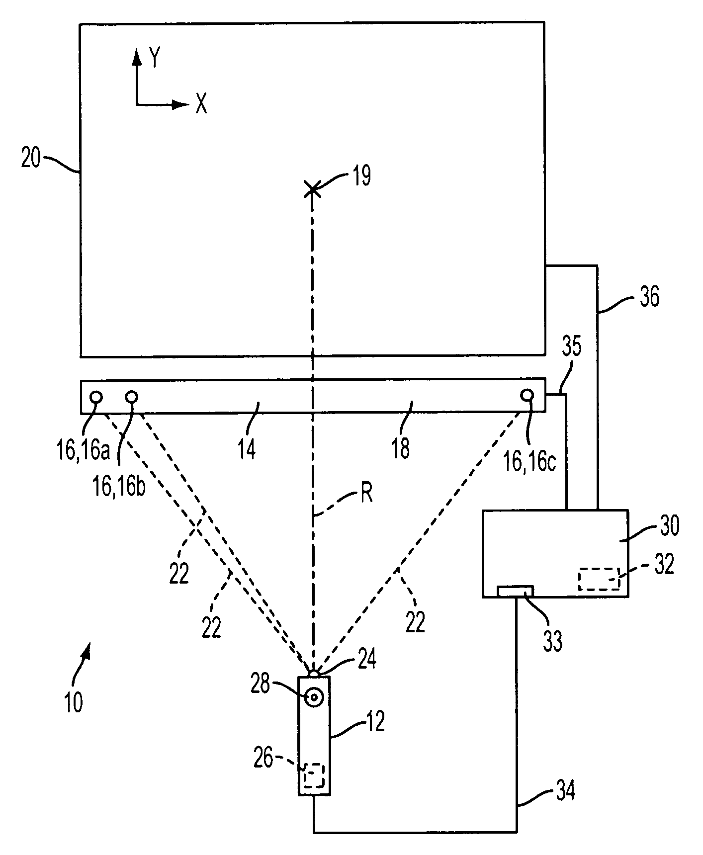
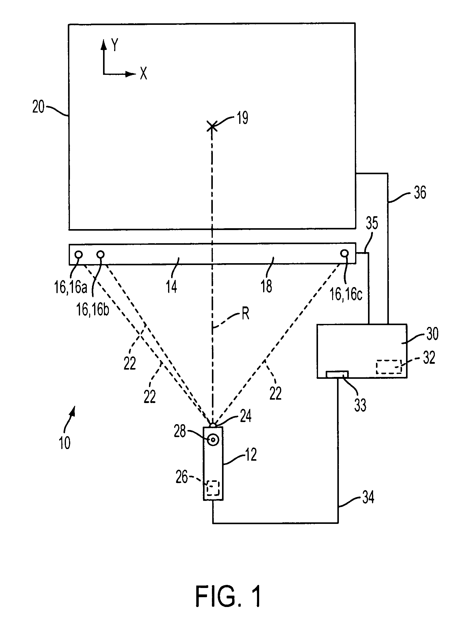
[0016]The present invention can include remote control systems that can distinguish predetermined light sources from stray light sources, such as environmental light sources and / or reflections.
[0017]FIG. 1 illustrates one embodiment of a remote control system of the present invention. Remote control system 10 can include remote control 12 and multiple predetermined light sources 16. Predetermined light sources 16 can be disposed in frame 18 to form light transmitter 14 or integrated with display 20. As used herein, light sources can either generate light or reflect light shined thereon. If light source(s) act as reflector(s), another light source can project light towards the reflector(s). The reflector(s) can reflect the light back to a photodetector. For example, the photodetector and the other light source can be disposed on remote control 12, whereas the reflector(s) can be disposed proximate to, near, on, or in display 20.
[0018]Remote control system 10 can permit a user to inte...
PUM
 Abstract
Description
Claims
Application Information