Knee airbag apparatus

a technology of airbags and knees, which is applied in the direction of pedestrian/occupant safety arrangements, vehicular safety arrangements, vehicle components, etc., can solve the problems of difficult suppression of the likely entry of the knee airbag, so as to improve the performance of restraining the knees and suppress the widening of the distance between the knees.

Inactive Publication Date: 2008-05-29
TOYOTA JIDOSHA KK
View PDF13 Cites 55 Cited by
  • Summary
  • Abstract
  • Description
  • Claims
  • Application Information

AI Technical Summary

Benefits of technology

[0009]According to the above-described aspects, for example, when the vehicle has a frontal collision, the knee airbag, which is disposed in the folded state inside the steering column cover, receives the gas, and is inflated and deployed from the inside of the steering column cover toward the knees of the occupant. Thus, the knee airbag restrains the knees. The thickness of the outer portions of the knee airbag, which are positioned outside the centers of the knees, is set to be larger than the thickness of the general portion at this time. The shape of the deployed knee airbag may be regulated such that the distance between the instrumental panel and the point closest to the rear of the vehicle in each of outer portions is larger than the distance between the instrument panel 22 and the point closest to the rear of the vehicle in the general portion of the knee airbag. Therefore, the outer portions suppress the widening of the distance between the knees.
[0010]In the knee airbag device according to the aspects, the knee airbag may include an instrument panel-side foundation cloth positioned close to an instrument panel when the knee airbag is deployed, an occupant-side foundation cloth positioned close to the occupant when the knee airbag is deployed, at least one right tether disposed in a right portion of the knee airbag, and at least one left tether disposed in a left portion of the knee airbag. Each of the at least one right tether and the at least one left tether may connect the instrument panel-side foundation cloth and the occupant-side foundation cloth, and may regulate a thickness of the knee airbag. First connection points at which the right and left tethers are connected to the instrument panel-side foundation cloth may be set to be outside second connection points at which the right and left tethers are connected to the occupant-side foundation cloth, with respect to a center of the knee airbag in a vehicle-width direction.
[0011]According to the above-described aspects, each of the right and left tethers connects the instrument panel-side foundation cloth and the occupant-side foundation cloth of the knee airbag. Also, the first connection points at which the right and left tethers are connected to the instrument panel-side foundation cloth are set to be outside second connection points at which the right and left tethers are connected to the occupant-side foundation cloth, with respect to the center of the knee airbag in the vehicle-width direction. Therefore, the outer portions are pulled toward the rear of the vehicle, as compared to the general portion. As a result, the shape of the deployed knee airbag is regulated such that the thickness of the outer portions is larger than the thickness of the general portion. The knees of the occupant contact the portion of the knee airbag, which is inside the outer portions, and thus the knees are restrained. Therefore, the outer portions suppress the widening of the distance between the knees of the occupant.
[0013]According to the above-described aspects, the knee airbag is folded such that the ridges of the pleats are oriented upward and downward in the vehicle-height direction, and then, right and left side portions of the knee airbag in the vehicle-width direction are rolled up toward the instrument panel. The folded knee airbag is stored inside the steering column cover. Therefore, although the thickness of the outer portions is larger than the thickness of the general portion when the knee airbag is deployed, it is possible to deploy the knee airbag in front of the knees of the occupant. Therefore, it is possible to improve the performance of restraining the knees by suppressing the widening of the distance between the knees.

Problems solved by technology

However, in the above-described knee airbag device, when a knee airbag is deployed between an instrument panel and knees of an occupant, the knee airbag is likely to enter an area between the knees in a vehicle-width direction.
Therefore, it is difficult to suppress the widening of the distance between the knees.

Method used


Image

  • Knee airbag apparatus
  • Knee airbag apparatus
  • Knee airbag apparatus

Examples


Embodiment Construction

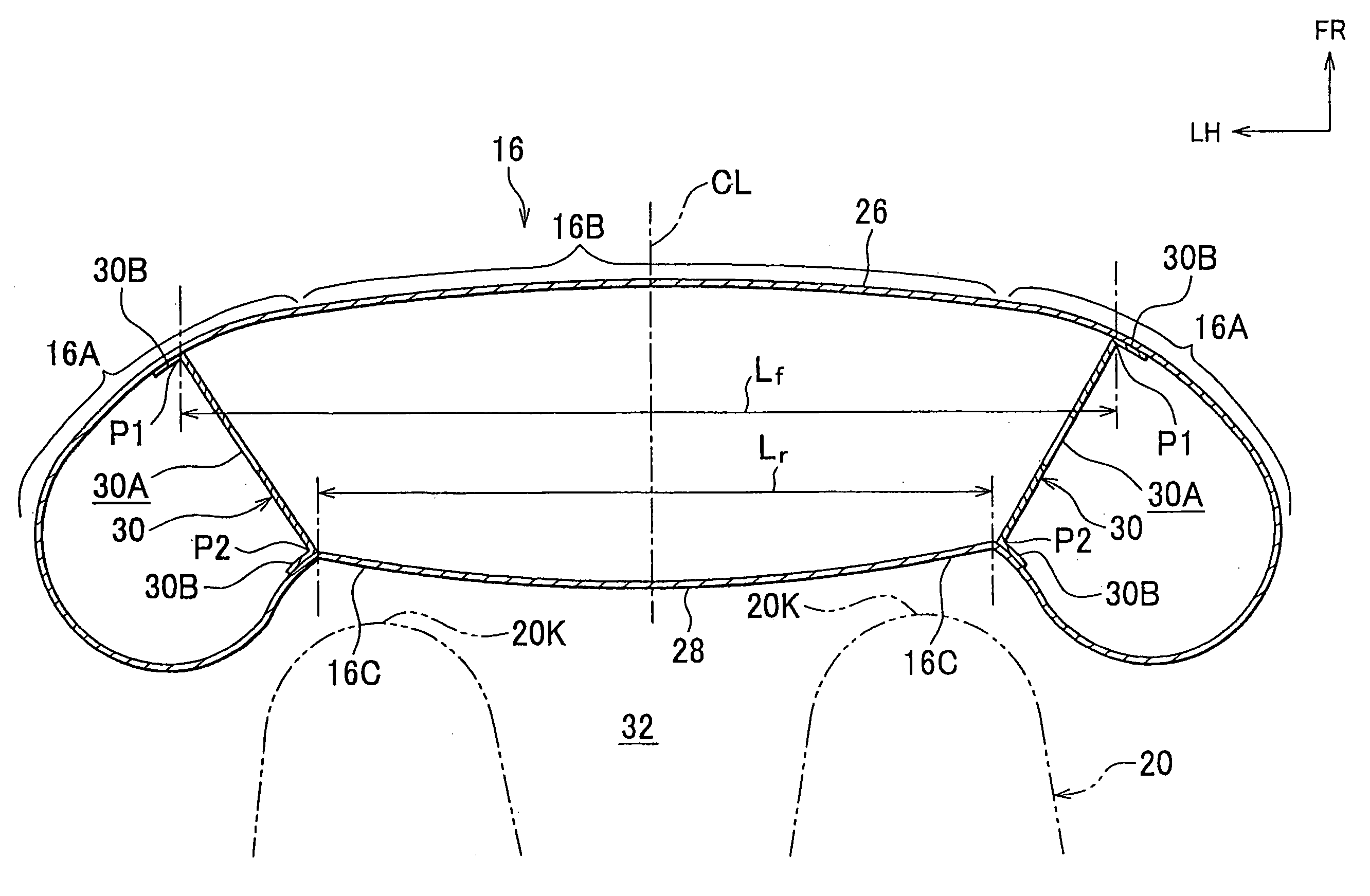
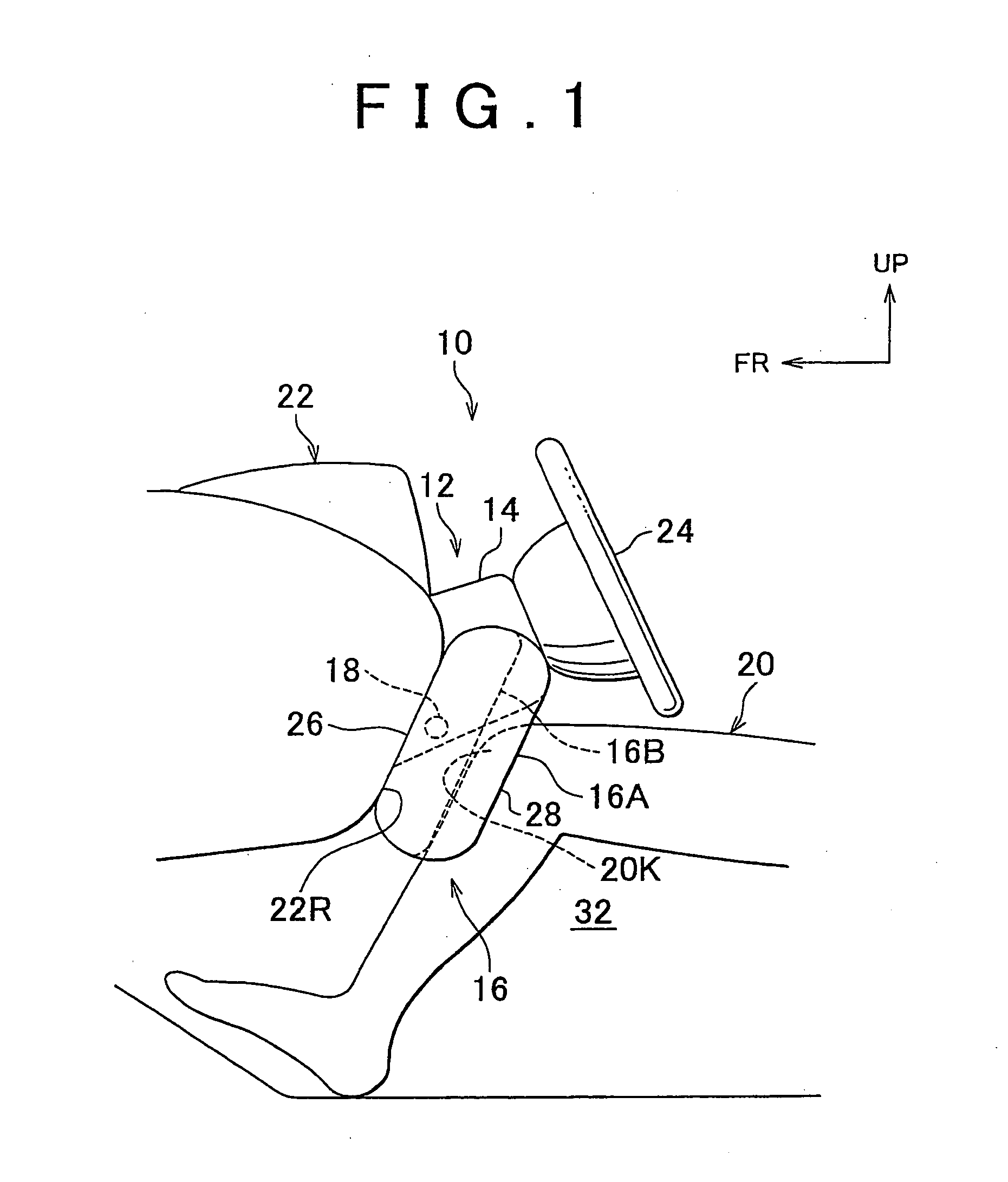
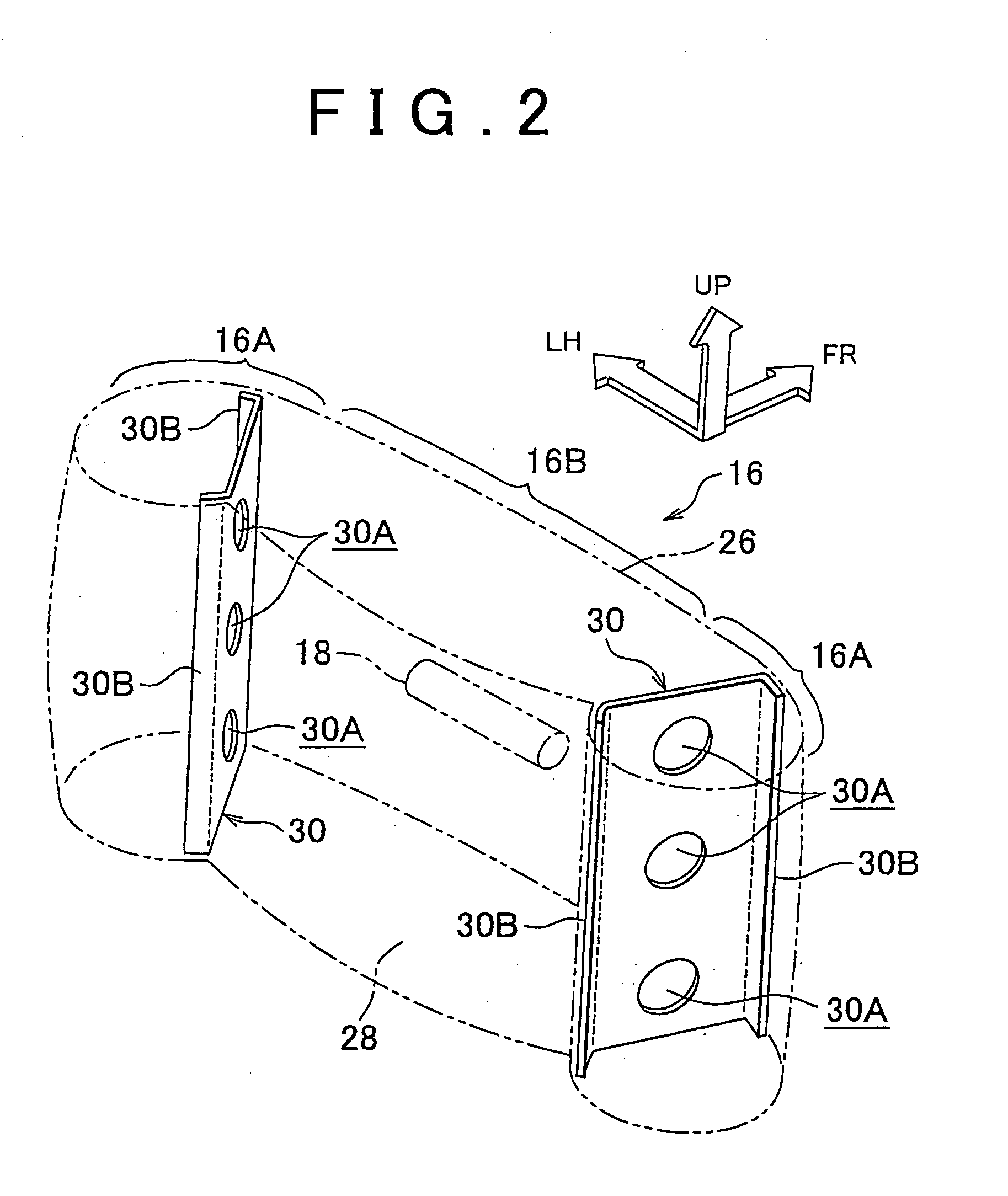
[0023]Hereinafter, an embodiment of the invention will be described with reference to the accompanying drawings. In FIG. 1, a knee airbag device 10 according to the embodiment includes a knee airbag 16. The knee airbag 16 is disposed in a folded state inside a steering column cover 14. For example, when the knee airbag 16 receives gas supplied from an inflator 18, the knee airbag 16 is inflated and deployed from the inside of the steering column cover 14 toward the knees 20K of an occupant 20, i.e., toward a vehicle cabin 32.

[0024]A steering column 12 covered by the steering column cover 14 includes a steering main shaft (not shown) and a column tube (not shown). The steering main shaft is disposed in the core of the steering column 12. The column tube, which covers the steering main shaft, is supported by a vehicle body. The front end portion of the steering column 12 is inserted through an opening portion (not shown) formed in an instrument panel 22. The rear end portion of the st...


PUM


Abstract

A knee airbag device includes a knee airbag that is disposed in a folded state inside a steering column cover. When the knee airbag receives gas, the knee airbag is inflated and deployed from an inside of the steering column cover toward knees of an occupant. The thickness of outer portions of the knee airbag, which are positioned outside centers of the knees when the knee airbag is deployed, is set to be larger than the thickness of a general portion of the knee airbag, which is positioned in front of the knees when the knee airbag is deployed.

Description

INCORPORATION BY REFERENCE[0001]The disclosure of Japanese Patent Application No. 2006-317685 filed on Nov. 24, 2006 including the specification, drawings and abstract is incorporated herein by reference in its entirety.BACKGROUND OF THE INVENTION[0002]1. Field of the Invention[0003]The invention relates to a knee airbag device.[0004]2. Description of the Related Art[0005]Japanese Patent Application Publication No. 2002-37003 (JP-A-2002-37003) describes a knee airbag device in which a knee airbag module is disposed inside a steering column cover that covers a steering column.[0006]However, in the above-described knee airbag device, when a knee airbag is deployed between an instrument panel and knees of an occupant, the knee airbag is likely to enter an area between the knees in a vehicle-width direction. Therefore, it is difficult to suppress the widening of the distance between the knees.SUMMARY OF THE INVENTION[0007]The invention suppresses widening of a distance between knees of ...

Claims


Application Information

Patent Timeline
Patent Type & Authority Applications(United States)
IPC IPC(8): B60R21/231B60R21/203B60R21/20B60R21/206B60R21/2338B60R21/237
CPCB60R21/203B60R21/206B60R21/233B60R2021/23382B60R2021/23169B60R2021/23324B60R21/2338
Inventor IMAMURA, KENJIFUKAWATASE, OSAMUSANADA, AKIYOSHI
Owner TOYOTA JIDOSHA KK
Why Eureka
Try Eureka