Robotic System

a robot and system technology, applied in the field of robot systems, can solve the problems of restricted robot motion, less amusement, and the inability of conventional robots to perform

Active Publication Date: 2008-05-29
FUTABA CORPORATION
View PDF3 Cites 0 Cited by
  • Summary
  • Abstract
  • Description
  • Claims
  • Application Information

AI Technical Summary

Benefits of technology

[0010]The present invention is to provide a robotic system capable of implementing various motions by a simple manipulation of the robotic system.
[0013]The control means responds to the control signal and drives the motors in such a way that each of the motions instructed by the switch operation section and the analog operation section is added. The motion instructed by the analog operation section corresponds to an attitude control motion of the robot. The attitude control motion may be the control motion to shift the barycenter position of the robot. The control means drives a motor that moves at least the ankle joint and the hip joint of the robot so as to shift the barycenter position. At least, a roll axis control motor and a pitch axis control motor may be mounted to each joint as a motor for controlling each ankle joint and each hip joint. According to the present invention, the robotic system that can implement various motions by a simple manipulation of the robotic system.

Problems solved by technology

However, the conventional robot can perform only regeneration of the motions allocated in advance to each operation section and an automatic attitude control motions utilizing a sensor such as a gyro-sensor.
Thus, the motions of the robot are restricted and less appealing in amusements.

Method used


Image

  • Robotic System
  • Robotic System
  • Robotic System

Examples


Embodiment Construction

[0019]A robotic system according to an embodiment of the present invention will be explained with reference to an example of a biped walking robot.

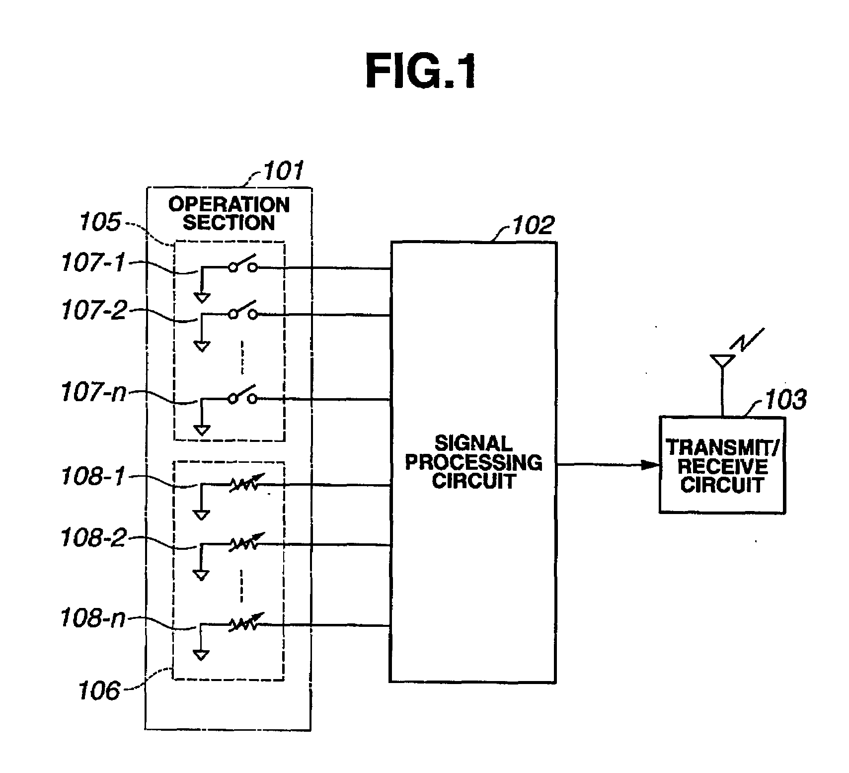
[0020]Referring to FIG. 1, the transmitter for remotely controlling a robot includes an operation section 101, a signal processing circuit 102, and a transmit / receive circuit 103. The operation section 101 includes an allocation operation instructor 105 for instructing allocated motions and an analog quantity instructor 106 for instructing the motions corresponding to an operation or manipulation amount. The allocation operation instructor 105 formed of switches, includes plural switch operation sections, such as, for example, button switches 107-1 to 107-n, each of which is on / off operated to indicate the allocated motions. Mutually different motions, such as walking motion, rising motion, and so on, are allocated to the switch operation sections 107-1 to 107-n, respectively. The analog quantity instructor 106 includes variable resistors...


PUM


Abstract

A robotic system is provided that enables easy manipulation and various operations. A walking operation allocated to a manipulated switch operation section is performed. Meanwhile, the right ankle roll axis control motor, the left ankle roll axis control motor, right hip joint roll axis control motor, and the left hip joint roll axis control motor are driven according to the operation amount of a manipulated analog operation section. Thus, the barycentric position of the robot is shifted to change the traveling direction of walking.

Description

CROSS REFERENCE TO RELATED APPLICATION[0001]This application claims the priority benefit of Japanese Patent Application No. 2006-282184 filed on Oct. 17, 2006.STATEMENT REGARDING FEDERALLY SPONSORED RESEARCH[0002]Not ApplicableBACKGROUND OF THE INVENTION[0003]1. Field of the Invention[0004]The present invention relates to robotic systems for remotely controlling robots.[0005]2. Description of the Related Art[0006]Conventionally, robotic systems for remotely controlling a robot have been developed for games or the like. An example of such a robotic system is disclosed in Japanese Patent Publication No. 2006-51586.[0007]When the conventional robot having a large number of joints, such as a humanoid robot, is remotely controlled, a switch having operation sections attached on a transmitter is on / off operated in such a way that the robot performs motions allocated in advance to each operation section.[0008]In order to perform the motions allocated in advance to each operation section th...

Claims


Application Information

Patent Timeline
Patent Type & Authority Applications(United States)
IPC IPC(8): B25J5/00B25J13/00
CPCB62D57/032B25J9/1689B25J9/06B25J13/02Y10S901/01
Inventor MIYASHIGE, MASAYUKISUZUKI, YASUYUKIUEMURA, CHIHIRO
Owner FUTABA CORPORATION
Why Eureka
Try Eureka