Telecommunications patching system that facilitates detection and identification of patch cords

Active Publication Date: 2008-05-29
COMMSCOPE INC
View PDF16 Cites 130 Cited by
  • Summary
  • Abstract
  • Description
  • Claims
  • Application Information

AI Technical Summary

Benefits of technology

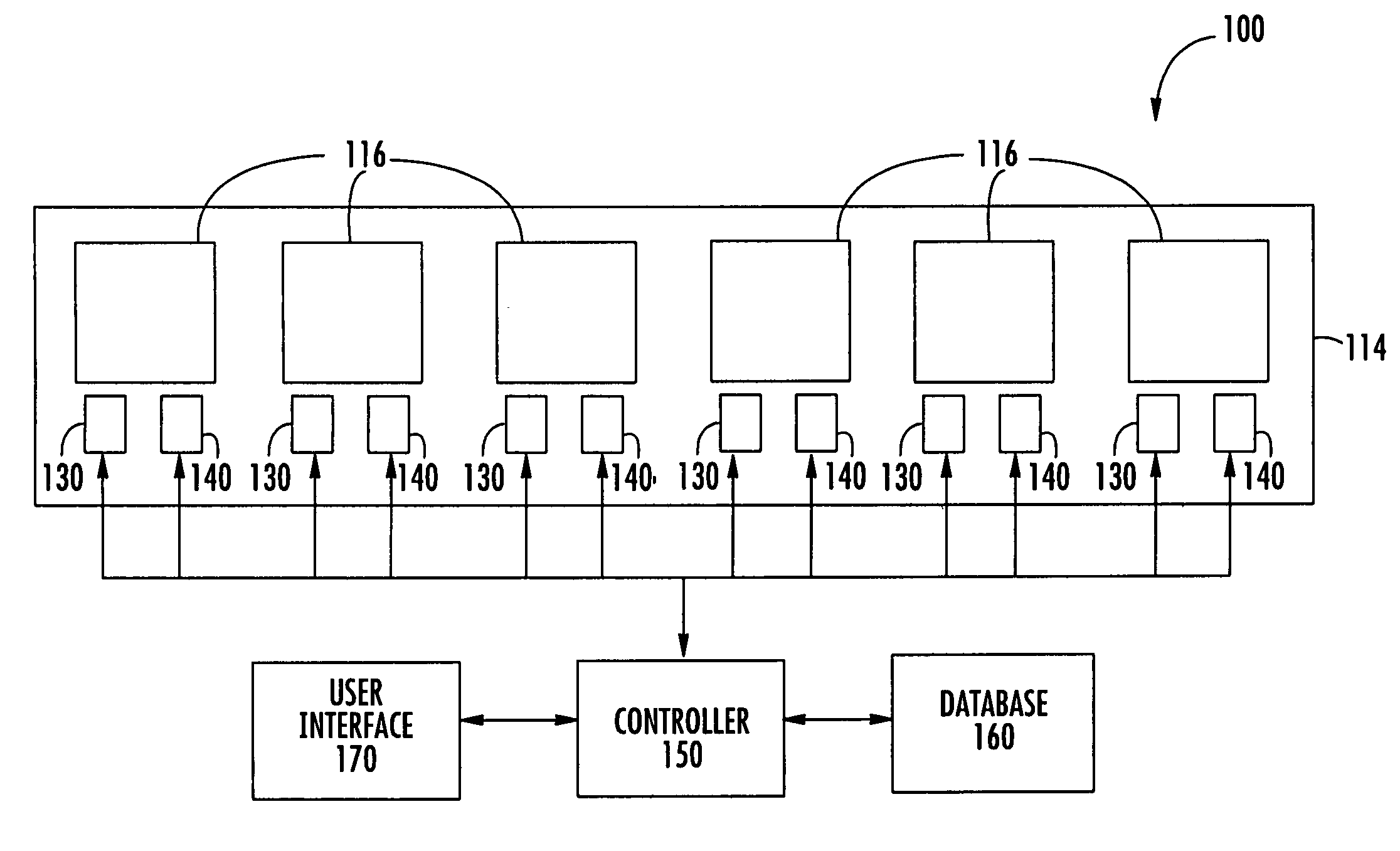
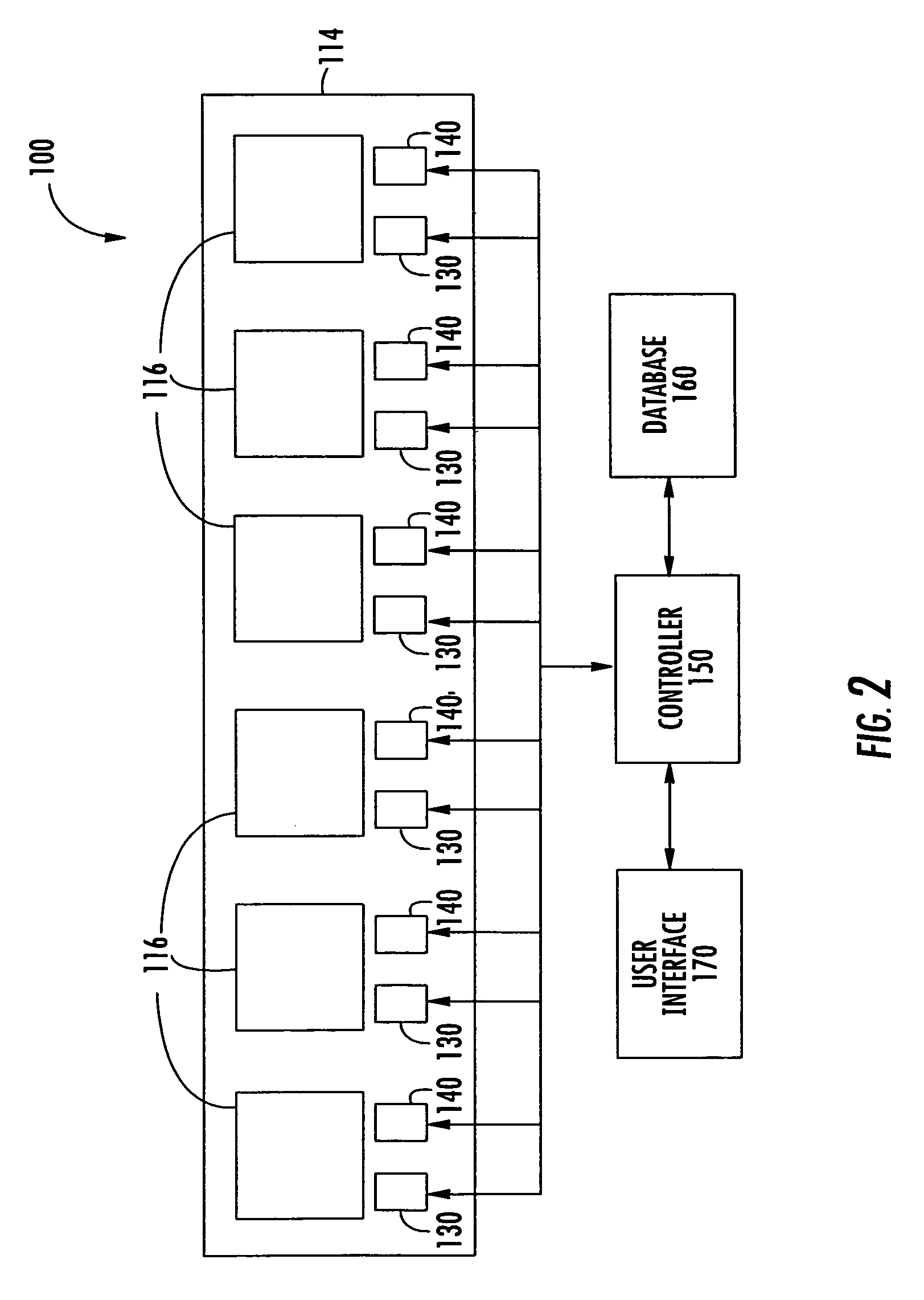
[0009]In view of the above discussion, a telecommunications patching system, according to some embodiments of the present invention, includes a patch panel comprising a plurality of connector ports and a plurality of patch cords configured to selectively interconnect pairs of the connector ports. Each patch cord has opposite ends and a respective connector secured to each end that is configured to be removably secured within a connector port. The connectors of a respective patch cord have the same unique identifier. The telecommunicatio

Problems solved by technology

When an employee changes office locations, it may not be desirable to provide that employee with new exchange numbers.
However, technicians may neglect to update the log each and every time a change is made.
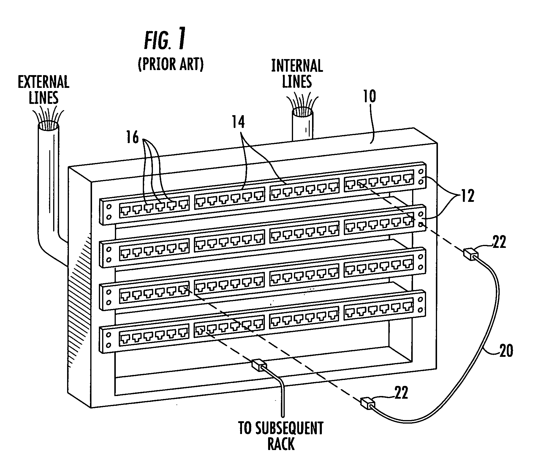
Inevitably, the log may become less than 100% accurate and a technician may not have a way of reading where each of the patch cords begins and ends.
It may take a significant amount of time for a technician to manually trace a particular patch cord, particularly within a collection of other patch cords.
Furthermore, manual tracing may n

Method used


Image

  • Telecommunications patching system that facilitates detection and identification of patch cords
  • Telecommunications patching system that facilitates detection and identification of patch cords
  • Telecommunications patching system that facilitates detection and identification of patch cords

Examples


Embodiment Construction

[0022]The present invention now is described more fully hereinafter with reference to the accompanying drawings, in which preferred embodiments of the invention are shown. This invention may, however, be embodied in many different forms and should not be construed as limited to the embodiments set forth herein; rather, these embodiments are provided so that this disclosure will be thorough and complete, and will fully convey the scope of the invention to those skilled in the art.

[0023]Like numbers refer to like elements throughout. In the figures, the thickness of certain lines, layers, components, elements or features may be exaggerated for clarity. Broken lines illustrate optional features or operations unless specified otherwise. All publications, patent applications, patents, and other references mentioned herein are incorporated herein by reference in their entireties.

[0024]The terminology used herein is for the purpose of describing particular embodiments only and is not inten...


PUM


Abstract

A telecommunications patching system includes a patch panel comprising a plurality of connector ports and a plurality of patch cords configured to selectively interconnect pairs of the connector ports. Each patch cord has opposite ends and a respective connector secured to each end that is configured to be removably secured within a connector port. The connectors of a respective patch cord have the same unique identifier associated therewith. A first sensor is located at each connector port and detects when a patch cord connector is inserted within, and removed from, a respective connector port. A second sensor is located at each connector port and reads the identifier of a patch cord connector inserted within a respective connector port. The first and second sensors are in communication with a controller that monitors and logs patch cord interconnections with the connector ports.

Description

FIELD OF THE INVENTION[0001]The present invention relates generally to telecommunications systems and, more particularly, to telecommunications patching systems.BACKGROUND OF THE INVENTION[0002]Many businesses have dedicated telecommunication systems that enable computers, telephones, facsimile machines and the like to communicate with each other through a private network and with remote locations via a telecommunications service provider. In most buildings, the dedicated telecommunications system is hard wired using telecommunication cables that contain conductive wire. In such hard wired systems, dedicated wires are coupled to individual service ports throughout the building. Conventionally, the wires from the dedicated service ports extend through the walls of the building to a telecommunications closet or closets. The telecommunications lines from the interface hub of a main frame computer and the telecommunication lines from external telecommunication service providers may also...

Claims


Application Information

Patent Timeline
IPC IPC(8): H04Q5/22G08B1/08
CPCH01R13/6683H04Q1/138H01R24/64H04Q1/14
Inventor GERMAN, MICHAEL G.CHOUDHURY, GOLAM M.MACAULEY, DANIEL W.SATTERTHWAITE, DANNY L.TUCKER, PETER T.
Owner COMMSCOPE INC
Why Eureka
Try Eureka