Active environment scanning method and device

a scanning method and active environment technology, applied in the field of image display, can solve the problems of time-consuming and computationally expensive techniques

Inactive Publication Date: 2008-05-29
HONEYWELL INT INC
View PDF22 Cites 10 Cited by
  • Summary
  • Abstract
  • Description
  • Claims
  • Application Information

AI Technical Summary

Benefits of technology

[0012]In a further embodiment, the location of each pair of eyes detected from the captured image data may be mapped to a particular angular region in the viewing embodiment. For example, each eye of each viewer may be mapped to a particular angular region. Furthermore, this map may be used for...

Problems solved by technology

However, such techniques are time consuming and computationally expensive, because they require mathematica...

Method used


Image

  • Active environment scanning method and device
  • Active environment scanning method and device
  • Active environment scanning method and device

Examples


Embodiment Construction

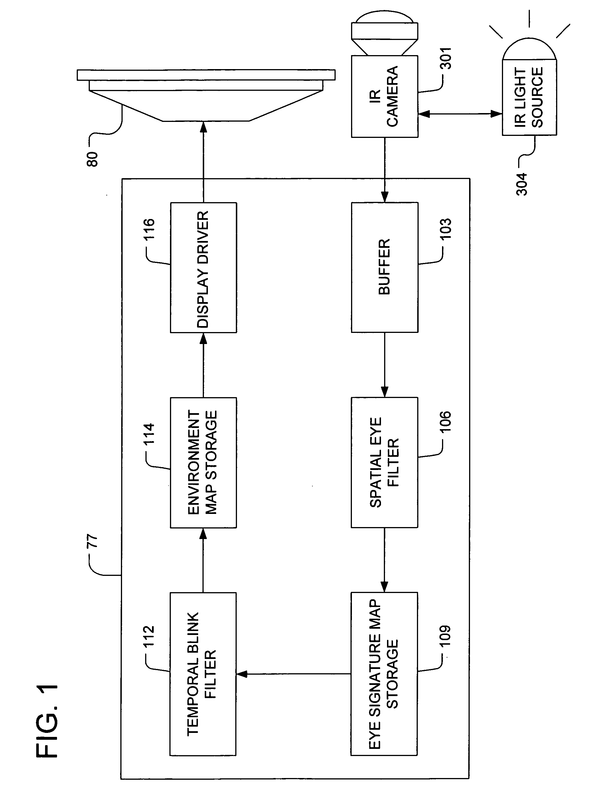
[0020]Aspects of the invention are more specifically set forth in the accompanying description with reference to the appended figures. FIG. 1 is a functional block diagram of a system for active scanning of the viewing environment of an image display panel, according to an exemplary embodiment of the present invention. As shown in FIG. 1, the system includes a display panel 80, a control unit 77, and an infrared (IR) camera 301.

[0021]As illustrated in FIG. 1, the control unit 77 includes the following functional units: an image buffer 103, a spatial eye filter 106; a memory unit for storing eye signature map 109; a temporal blink filter 112, a memory unit for storing a map of the viewing environment 114, and a display driver 116. The control unit 77 may be connected to a display panel 80, an infrared (IR) camera 301 (or other type of image capture device), and an IR light source 304 (or, possibly, a visible flash source). It should be noted that FIG. 1 is merely a functional block d...


PUM


Abstract

Methods and apparatuses are used for segmenting a viewing environment of an image display device (80) into angular regions based on the current positioning of viewers. Image data of the viewing environment may be captured and analyzed to detect possible regions (400) exhibiting the red-eye effect. These regions may be paired off, and each pair may be verified as corresponding to a viewer's eyes based on whether they exhibit the characteristics of blinking.

Description

BACKGROUND OF THE INVENTION[0001]1. Field of the Invention[0002]The present invention relates to image display, and more particularly, to techniques for mapping an angular viewing area of an image display panel according to viewer position.[0003]2. Description of the Related Art[0004]It is contemplated that image display panels may be designed for enhanced operation based on a detailed knowledge of the viewer's position.[0005]For example, it is contemplated that an image display panel could display three-dimensional (3D) images, without requiring the user to wear special 3D glasses, as described in copending U.S. patent application Ser. No. ______ (Docket No. H00011896), entitled “Directional Display,” filed on the same date and by the same inventor as the present application, the entire contents of which are incorporated herein by reference. This application describes a display panel designed to create a 3D visual effect by precisely aiming different images toward the left and righ...

Claims


Application Information

Patent Timeline
IPC IPC(8): G06K9/34
CPCG06K9/00597G06F3/013G06V40/18
Inventor CERNASOV, ANDREI
Owner HONEYWELL INT INC
Why Eureka
Try Eureka