Relay device and ultrasonic-surgical and electrosurgical system

a technology of ultrasonic surgery and electrosurgical system, which is applied in the field of electrosurgical system and ultrasonic surgery, can solve the problems of increasing the time required for surgery and complicated operation of the operator

Inactive Publication Date: 2008-05-29
OLYMPUS MEDICAL SYST CORP
View PDF5 Cites 277 Cited by
  • Summary
  • Abstract
  • Description
  • Claims
  • Application Information

AI Technical Summary

Benefits of technology

[0009]The present invention provides a relay device for relay between a single switch unit and each of an ultrasonic surgical device and an electrosurgical device, the switch unit being used for on/off control of outputs of the ultrasonic surgical device and the electrosurgical device, the ultrasonic surgical device and the electrosurgical device being connected to an ultrasonic/high-frequency treatment instrument capable of performing a treatment using ultrasonic vibration in accordance with an ultrasonic signal supplied from the ultrasonic surgical device and performing a treatment using high-frequency current in accordance with a high-frequency signal supplied from the electrosurgical device. The relay device includes the following components: a switch detection unit for detecting the turn-on/off of the switch unit; a switch element for outputting a switch signal for on/off control of the ultrasonic signal and the high-frequency signal to each of the ultrasonic surgical device and the electrosurgical device in accordance with an output signal of the switch detection unit; a control unit for performing on/off control of the switch signal of the switch element in accordance with the output signal of the switch detection unit to control at least one of an output timing and an output mode of each of the ultrasonic signal and the high-frequenc

Problems solved by technology

Under the above-described circumstances, as the number of surgical devices increases, the operator's manipulation becomes

Method used


Image

  • Relay device and ultrasonic-surgical and electrosurgical system
  • Relay device and ultrasonic-surgical and electrosurgical system
  • Relay device and ultrasonic-surgical and electrosurgical system

Examples


first embodiment

[0036]A first embodiment of the present invention will now be described with reference to FIGS. 1 to 9.

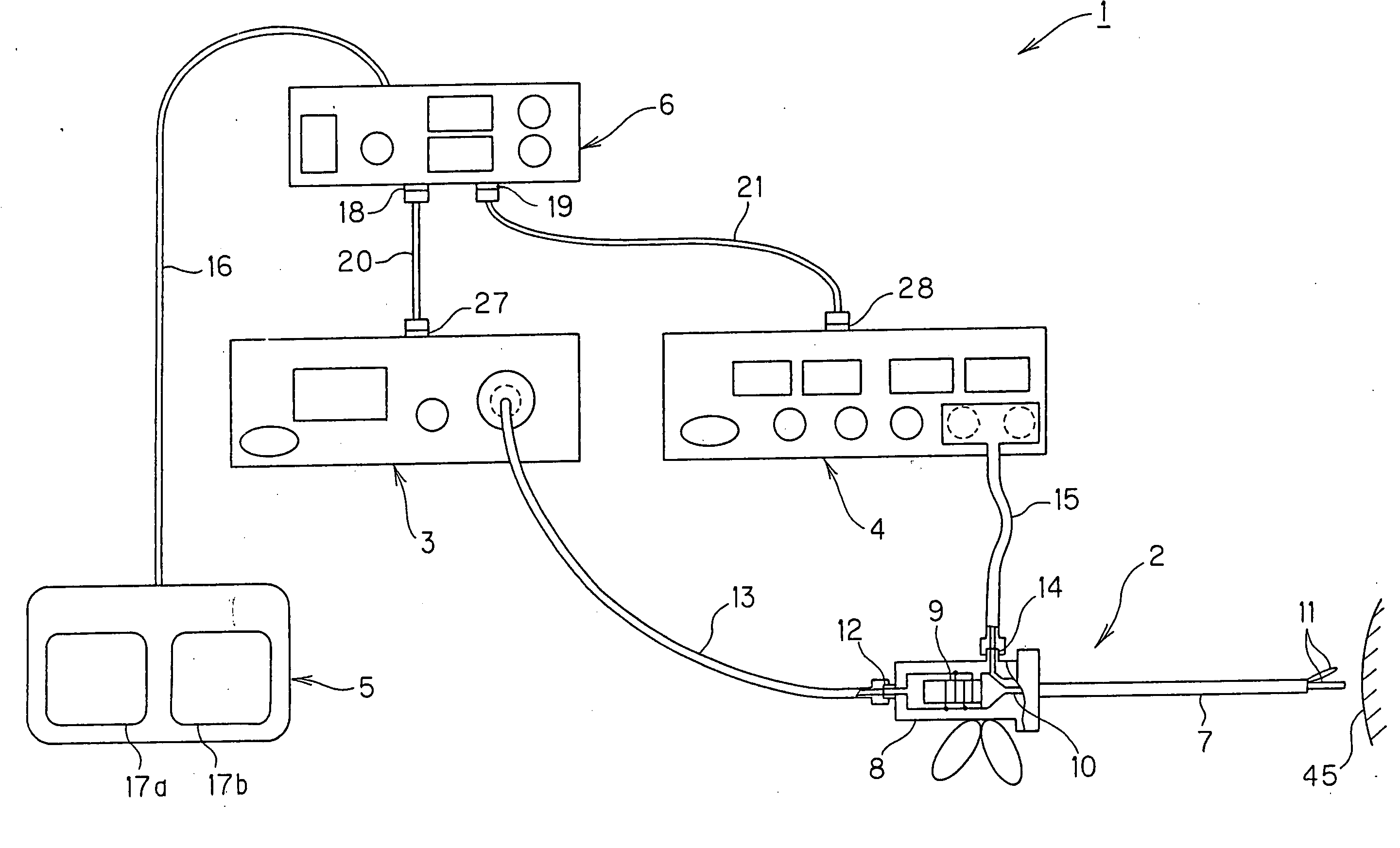
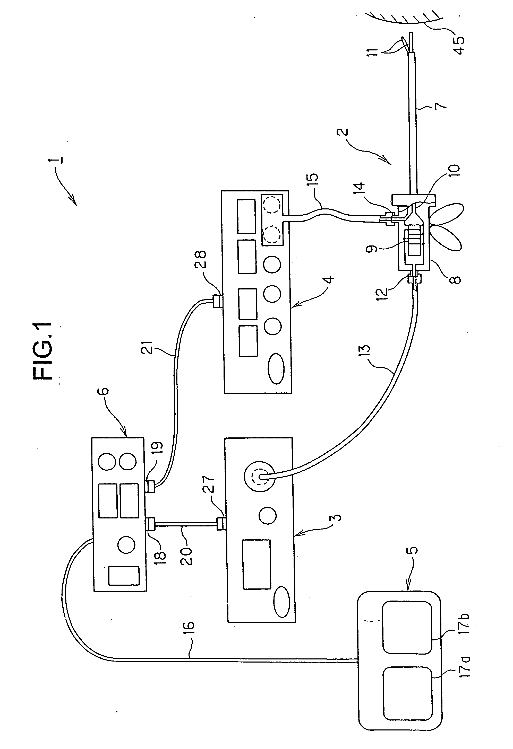
[0037]FIG. 1 shows a structure of an ultrasonic-surgical and electrosurgical system including a relay device according to a first embodiment of the present invention. It is an object of the present invention to provide a relay device that is applicable in the use of an existing ultrasonic surgical device and an existing electrosurgical device and is capable of improving the operability of the devices, and an ultrasonic surgical and electrosurgical system including the relay device.

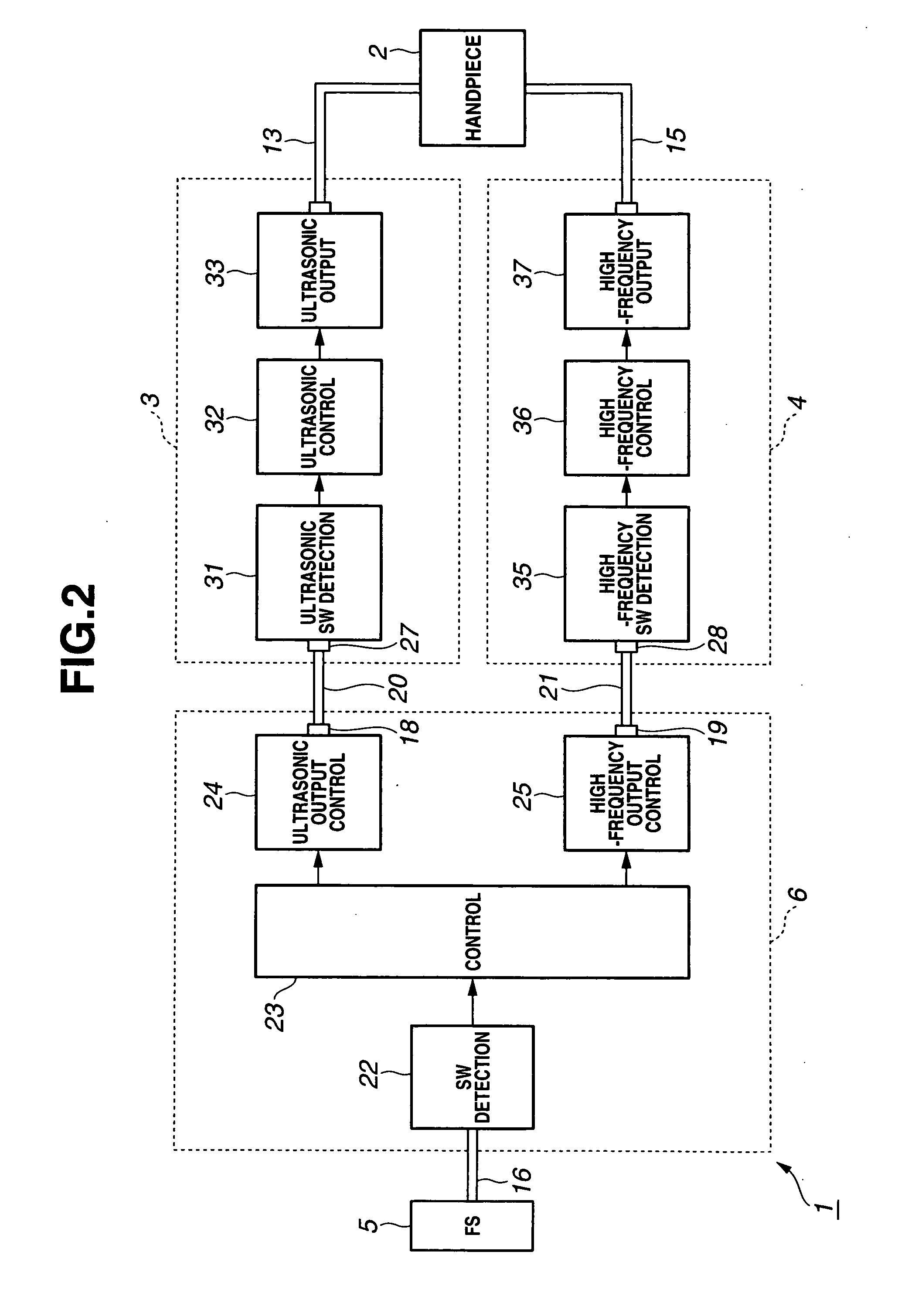
[0038]More specifically, the relay device according to the present invention is capable of controlling at least one of an output timing and an output mode of each of the ultrasonic surgical device and the electrosurgical device through a single switch unit or element.

[0039]Referring to FIG. 1, an ultrasonic-surgical and electrosurgical system 1 according to the first embodiment of the present invention in...

second embodiment

[0144]A second embodiment of the present invention will now be described with reference to FIGS. 10 to 14C. The fundamental structure of an ultrasonic-surgical and electrosurgical system according to the second embodiment is the same as that according to the first embodiment. The ultrasonic-surgical and electrosurgical system according to the present embodiment includes a relay device 6B partially different from the relay device 6 of the system 1 in FIGS. 1 and 2.

[0145]As will be described below, the relay device 6B according to the present embodiment further has parameter setting means that is not included in the relay device 6 according to the first embodiment. The parameter setting means readily changes an output control mode and an output timing pattern.

[0146]A user, e.g., an operator, changes settings on the parameter setting means so that an ultrasonic surgical device 3 and an electrosurgical device 4 can be operated in output modes and output timing patterns.

[0147]FIG. 10 sho...

third embodiment

[0191]A third embodiment of the present invention will now be described with reference to FIGS. 15 to 18D. The fundamental structure of an ultrasonic-surgical and electrosurgical system according to the present embodiment is similar to that according to the first embodiment. A relay device 6C according to the present embodiment differs from the relay device 6 in that the device 6C further includes communication means for communicating with an ultrasonic surgical device.

[0192]The ultrasonic-surgical and electrosurgical system according to the present embodiment includes an ultrasonic surgical device 3C instead of the ultrasonic surgical device 3 in the first embodiment. The ultrasonic surgical device 3C includes communication means for communicating with the relay device 6C.

[0193]According to the present embodiment, before the ultrasonic surgical device 3C drives a handpiece 2 to generate ultrasonic vibration, a resonance frequency (resonance point) of an ultrasonic transducer 9 disp...


PUM


Abstract

A relay device relays signals between a single switch unit and each of an ultrasonic surgical device that supplies an ultrasonic signal and an electrosurgical device that supplies a high-frequency signal, the switch unit being used for on/off control of outputs of the ultrasonic surgical device and the electrosurgical device, the ultrasonic surgical device and the electrosurgical device being connected to an ultrasonic/high-frequency treatment instrument capable of performing an ultrasonic treatment using ultrasonic vibration in accordance with the supplied ultrasonic signal and performing a high-frequency treatment in accordance with the supplied high-frequency signal. The relay device includes a switch detection unit for detecting the turn-on/off of the switch unit, a switch element for outputting a switch signal, which is used for on/off control of outputs of the ultrasonic signal and the high-frequency signal, to each of the ultrasonic surgical device and the electrosurgical device in accordance with a detection output of the switch detection unit, and a control unit for performing on/off control of the switch signal of the switch element in accordance with the detection output to control at least one of an output timing and an output mode of each of the ultrasonic signal and the high-frequency signal.

Description

BACKGROUND OF THE INVENTION[0001]1. Field of the Invention[0002]The present invention relates to a relay device connected to an ultrasonic surgical device and an electrosurgical device and an ultrasonic-surgical and electrosurgical system including the relay device.[0003]2. Description of the Related Art[0004]Conventionally, surgeries use surgical devices including various handpieces, such as an ultrasonic scalpel and an electric scalpel, for use in tissue ablation and simultaneous hemostasis.[0005]An ultrasonic surgical device and an electrosurgical device, serving as surgical devices, are individually operated. An operator has to manipulate switches dedicated to the respective devices to control the devices and operate handpieces connected to the devices.[0006]Under the above-described circumstances, as the number of surgical devices increases, the operator's manipulation becomes more complicated. Unfortunately, changing a handpiece to another one results in an increase in time re...

Claims


Application Information

Patent Timeline
IPC IPC(8): A61B17/32A61B18/12
CPCA61B17/320092A61B18/1206A61B18/1445A61B2017/00017A61N7/02A61B2017/00154A61B2017/00199A61B2017/00212A61B2017/00106A61B2017/320095A61B2017/320093
Inventor TAHARA, NAOKOSHIMIZU, KOH
Owner OLYMPUS MEDICAL SYST CORP
Why Eureka
Try Eureka