Method for placing a medical device at a bifurcated conduit

a medical device and bifurcation technology, applied in the field of devices, can solve the problems of difficult placement of unibody devices in bifurcations, difficult delivery of unibody devices through a small diameter sheath or catheter to the bifurcation site, and adverse consequences, so as to improve the delivery effect, minimize the effect, and improve the effect of torsional compliancy

Active Publication Date: 2008-05-29
CARDINAL HEALTH SWITZERLAND 515 GMBH
View PDF32 Cites 16 Cited by
  • Summary
  • Abstract
  • Description
  • Claims
  • Application Information

AI Technical Summary

Benefits of technology

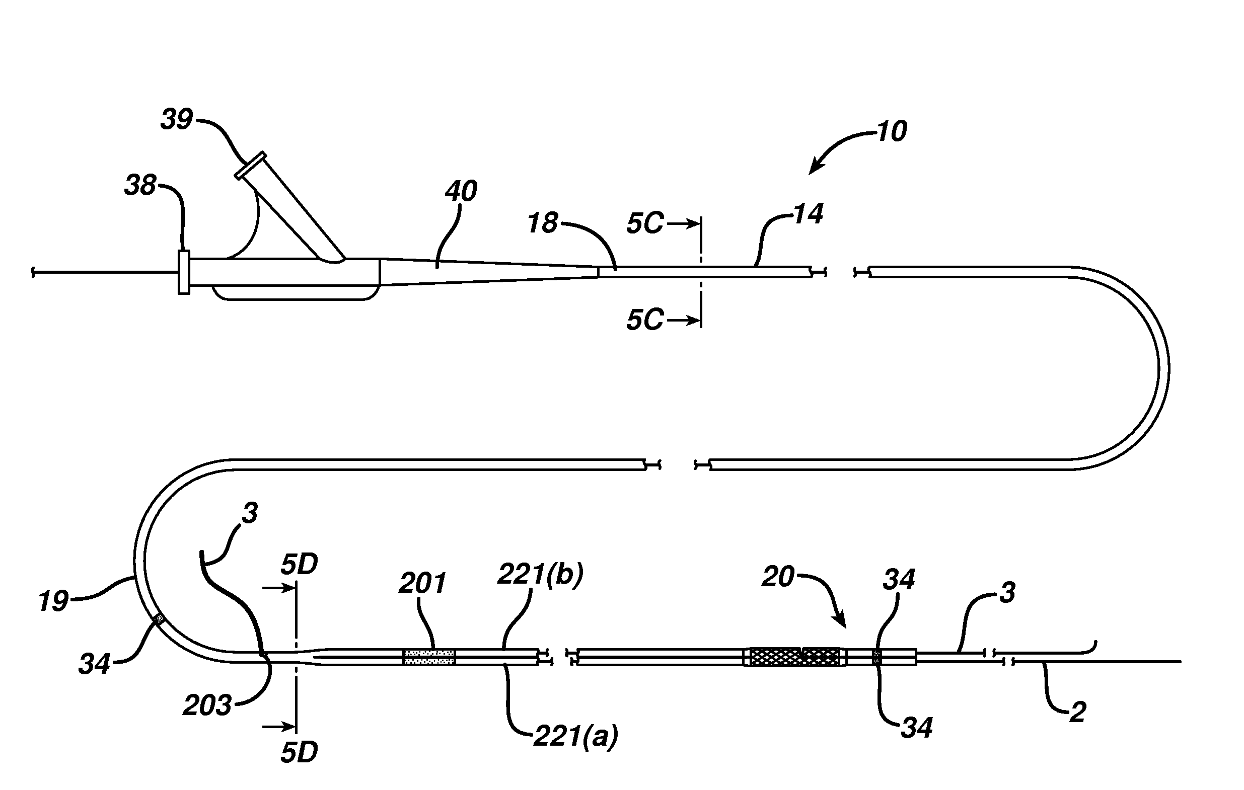
[0013]A distal portion of the catheter shaft splits into two expansion members each containing a guidewire lumen and an inflation lumen. The guidewire lumens are in communication with the Rx lumens of the mid-portion. Alternatively, at least one guidewire lumen may be in communication with the OTW lumen of the mid-portion and proximal portion. The distal portion of the catheter includes an inflation lumen in fluid communication with the inflation lumen of the proximal portion and mid-portion. In one embodiment, the inflation lumen splits at its distal end to communicate with each expansion member and provide for simultaneous expansion. Alternatively, two inflation lumens are provided along the length of the catheter device allowing for communication with multiple inflation devices providing for independent expansion of the members.
[0014]It is desirable to have the proximal portions of the shaft be flexible enough to allow for navigation through a body conduit but rigid enough to prevent kinking. In contrast, the distal portion of the shaft proximal to the delivery apparatus (e.g. stents) is significantly more flexible and torsionally compliant than sections proximal thereto in order to allow rotation of the distal portion of the shaft to align with the branch vessel(s) as well as enhance deliverability. For example, as the distal end is advanced over the guide wires, it will follow the wires, which have been advanced into the main and side branches, to obtain proper orientation. In order to minimize the effects due to the differing torsional properties of the distal and proximal portions of the shaft, a torsional transfer section is included. This section torsionally separates the two portions of the shaft through it's increased torsional compliancy and absorbs possible torque from the proximal end isolating it from transfer to the distal portion.
[0015]The expansion members may comprise at least two balloons located at the distal ends of the distal portions of the catheter. A first balloon is configured to extend into a side branch vessel and is generally shorter than a second balloon. Varying the length of the two balloons optimizes cooperation between the balloons by minimizing overlap to match bifurcation anatomy. Alternatively, at least one of the two balloons may be utilized that has stepped expansion diameters along its length such that one portion of the balloon has a smaller expansion diameter proximally than distally. This also helps to better match bifurcation anatomy if two similar length balloons are used.
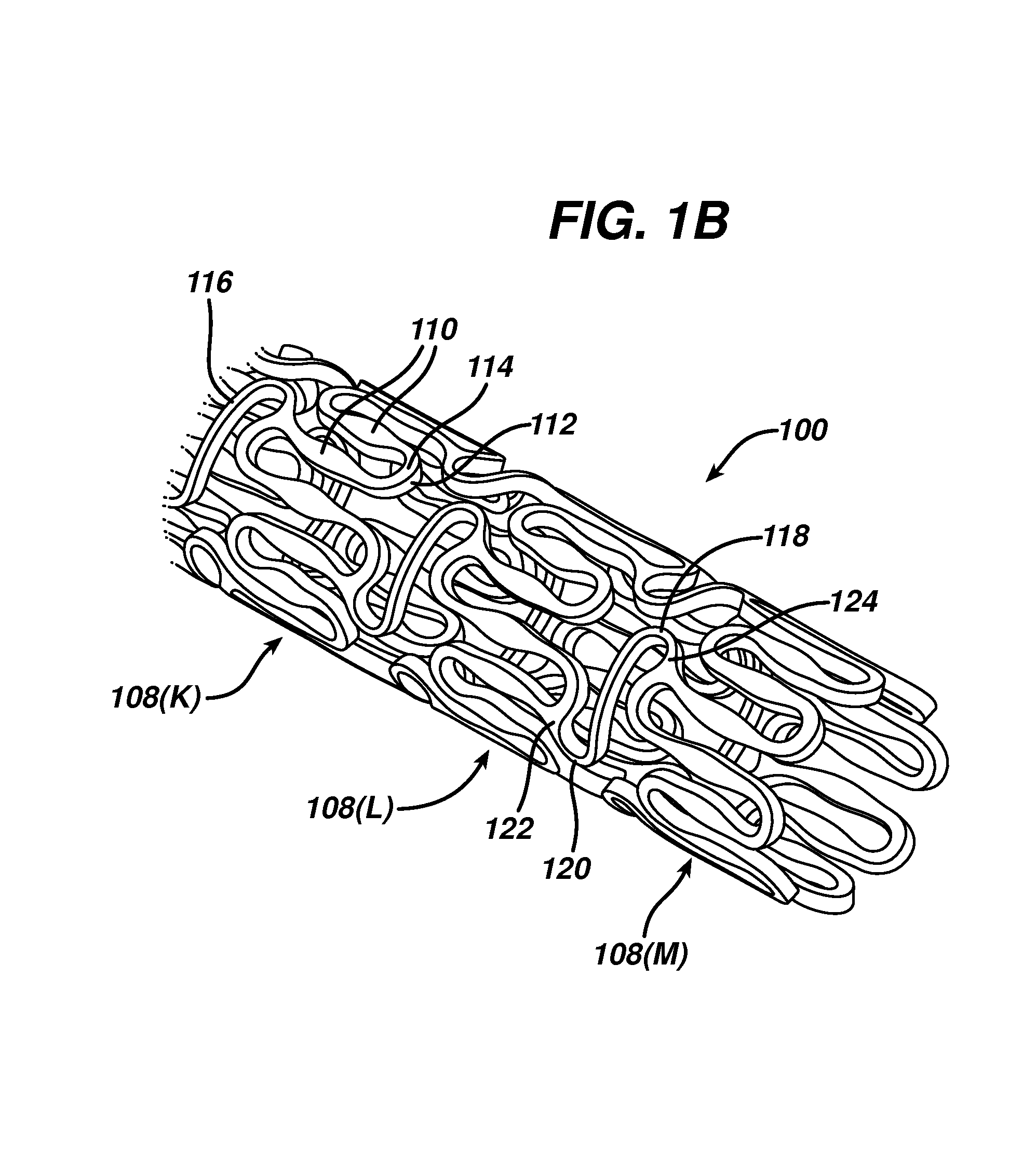
[0016]A first and second stent are mounted on the ends of the catheters. The first and second stent generally comprise a series of struts that are joined together by round joints to form hoops or elements. Adjacent hoops or elements are joined together by a plurality of bridges. The bridges are shaped to allow for the stent to flex in a longitudinal (?) direction. The round joints join the struts together in a manner that allows the stent to assume a first, smaller diameter and a second, larger diameter.
[0018]A distal torque transmission element is positioned between the first stent and the second stent. This element mitigates device wrapping caused by the transmission of rotation from the more flexible distal leg portion of the stents to the more rigid proximal portion of the first stent. Without this element, rotational “kinking” of the stents can occur due to the rapid transition in torsional stiffness of the device. In one embodiment of the invention, the distal portion of the side branch is coupled to the proximal end of main branch. This may be accomplished by a wire, coil, tube or the like that joins the two balloon / stent components. Alternatively, the stent can include a temporary mechanical connection, i.e. a strut or tab

Problems solved by technology

These conduits can become diseased or clogged causing severe, adverse consequences.
It is difficult to place a device in a bifurcation since the vessel bifurcations generally have circumferential asymmetry requiring the device to be precisely positioned, provide adequate coverage of the diseased area, provide access to any diseased area located distal to the bifurcation, and maintain vessel patency in order to allow adequate blood flow.
Because of their shape, unibody devices are difficult to deliver through a small diameter sheath or catheter to the bifurcation site.
Another delivery problem experienced with unibody designs is wrapping of the wire and device due to the contortions experienced during delivery.
Finally, unibody designs are difficult to manufacture as most stents are constructed from a single tube or sheet of material.
A unibody device is also difficult to coat with substances such as drugs or other therapeutic agents that are useful in preventing restenosis.
A drawback to this approach is that it requires multiple steps to place the branched stent within the bifurcation.
If the second or side branch stent is not accurately positioned and contacts the main branch stent, the opening of the main branch stent may become compromised.
The delivery catheter system of Callol fails to disclose a method for accomplishing this.
This prevents complete delivery of the devices and can result in the clinician having to withdraw a wire and rewire the vessel.
Secondly, solely relying on two wires for orientation is insufficient to guarantee full and proper alignment of the entire medical apparatus with the side branch ostium.
While this method ensures that guide wires are accurately placed in the main vessel and branch vessel, it is still only useful for placing a single stent to treat the main vessel.
For example, the problems associated with wire wrapping are still present.
Currently, there is no apparatus, delivery system or method that can simultaneously place separate stents in a vessel bifurcation.

Method used


Image

  • Method for placing a medical device at a bifurcated conduit
  • Method for placing a medical device at a bifurcated conduit
  • Method for placing a medical device at a bifurcated conduit

Examples


Embodiment Construction

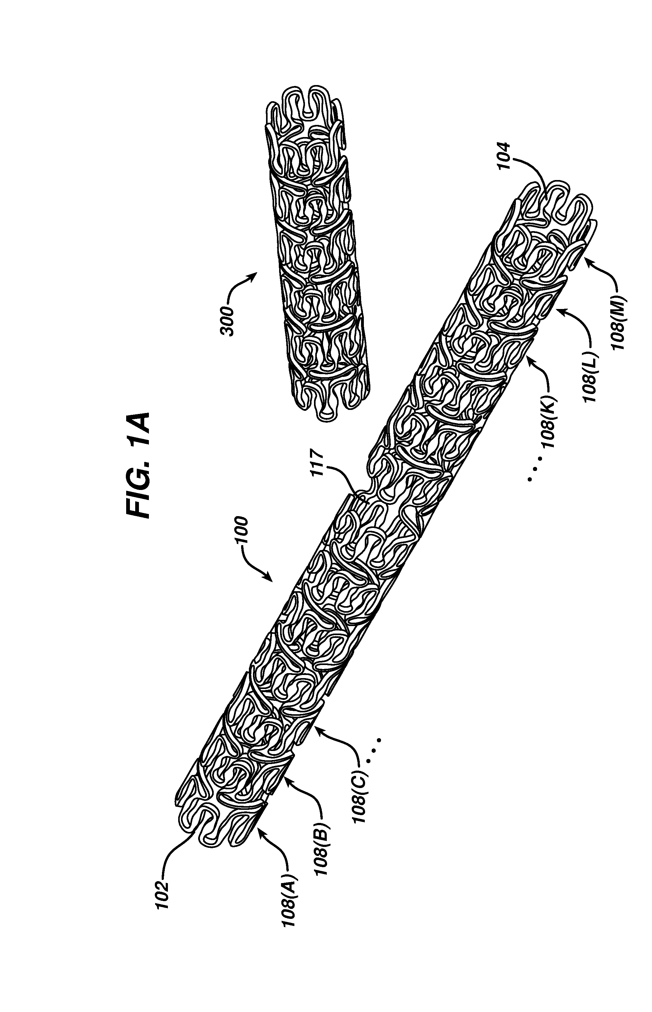
[0043]An apparatus, system and method for treating a diseased conduit of a human body at a bifurcation will be described with reference to the FIG. 1A shows a first stent 100 and a second stent 300 that may be placed within a conduit, for example at a vessel bifurcation. Although FIG. 1A shows stent 100 and 300 to be substantially similar, it is important to note that each of stents 100 and 300 may have different characteristics. For example, stents 100 and 300 may be constructed from different materials, have different geometries and / or be coated with or have different agents embedded therein. In particular, stent 100 may be a bare metal stent while stent 300 is a polymeric stent coated with a therapeutic agent or having the therapeutic agent embedded in its polymer matrix. Additionally, stent 100 may be coated with a therapeutic agent, but have a wider diameter or geometry, the characteristics of which are discussed in greater detail below, than stent 300.

[0044]For ease of descrip...


PUM


Abstract

A method for treating a diseased body conduit at a bifurcation point is provided. A system having devices mounted thereon is advanced into the bifurcated region of the conduit. The system includes a delivery means, such as a catheter having a shaft with varying torsional properties along its length and a delivery apparatus mounted at its distal end. A distal end of the delivery means can be inserted into the main branch and at least one side branch of a vessel bifurcation. The distal end includes at least two expansion members having expandable devices or prostheses mounted thereon. One device is configured such that one expansion member extends through the length of the scaffold while the other expansion member extends through the side-structure of the scaffold. A second scaffold is mounted on the expansion member extending through the side-structure of the first scaffold. The devices are positioned within the main and side branches of the bifurcation and are expanded.

Description

FIELD OF THE INVENTION[0001]This invention generally relates to devices that are used to treat disease states of the human vasculature. In particular, this invention relates to a device used to treat disease states in a bifurcating region of a body lumen such as a coronary artery or a billiary duct.BACKGROUND OF THE INVENTION[0002]In the human body there are numerous conduits, for example blood vessels and ducts that carry necessary fluids to internal organs or allow for the excretion of those fluids. These conduits can become diseased or clogged causing severe, adverse consequences. One example of a disease afflicting a body conduit is arteriosclerosis, caused by the presence of matter on or in the inner wall of blood vessels resulting in occlusion of the vessel. One possible treatment for arteriosclerosis is Percutaneous Transluminal Coronary Angioplasty (PTCA), which often is accompanied by the placement of a device, such as a stent.[0003]Arteriosclerosis and related diseases can...

Claims


Application Information

Patent Timeline
Patent Type & Authority Applications(United States)
IPC IPC(8): A61F2/06
CPCA61F2/856A61F2/91A61F2250/006A61F2/958A61F2250/0039A61F2/954
Inventor KREVER, MATTHEWBURGERMEISTER, ROBERTSCHULTING, EDWINVAN ERP, WILHELMUSDIRKS, RICHARD
Owner CARDINAL HEALTH SWITZERLAND 515 GMBH
Why Eureka
Try Eureka