Box structure

a box and structure technology, applied in the field of box structure, can solve the problems of loss of cover, inconvenience in use, and inconvenient use of box structure, and achieve the effects of convenient hanging, poor box connection structure, and convenient use of box

Inactive Publication Date: 2008-06-05
WANG KUANG PIN
View PDF5 Cites 15 Cited by
  • Summary
  • Abstract
  • Description
  • Claims
  • Application Information

AI Technical Summary

Benefits of technology

[0005]A primary object of the present invention is to provide a box structure for solving the above-mentioned problems. Structures and resisting portions are respectively installed on a receiving box and a cover body for enabling them to slide relatively. Accordingly, the receiving box can be opened or closed by a stepwise movement between the cover body and the receiving box while the cover body is mounted on the receiving box. Therefore, the received article can be convenientl

Problems solved by technology

However, such a box structure, having to separate the cover and box, often suffers the problems of difficulty in taking out the article received therein and losing the cover.
However, after a period of usage, the receiving box 8 will be p

Method used


Image

  • Box structure
  • Box structure
  • Box structure

Examples


second embodiment

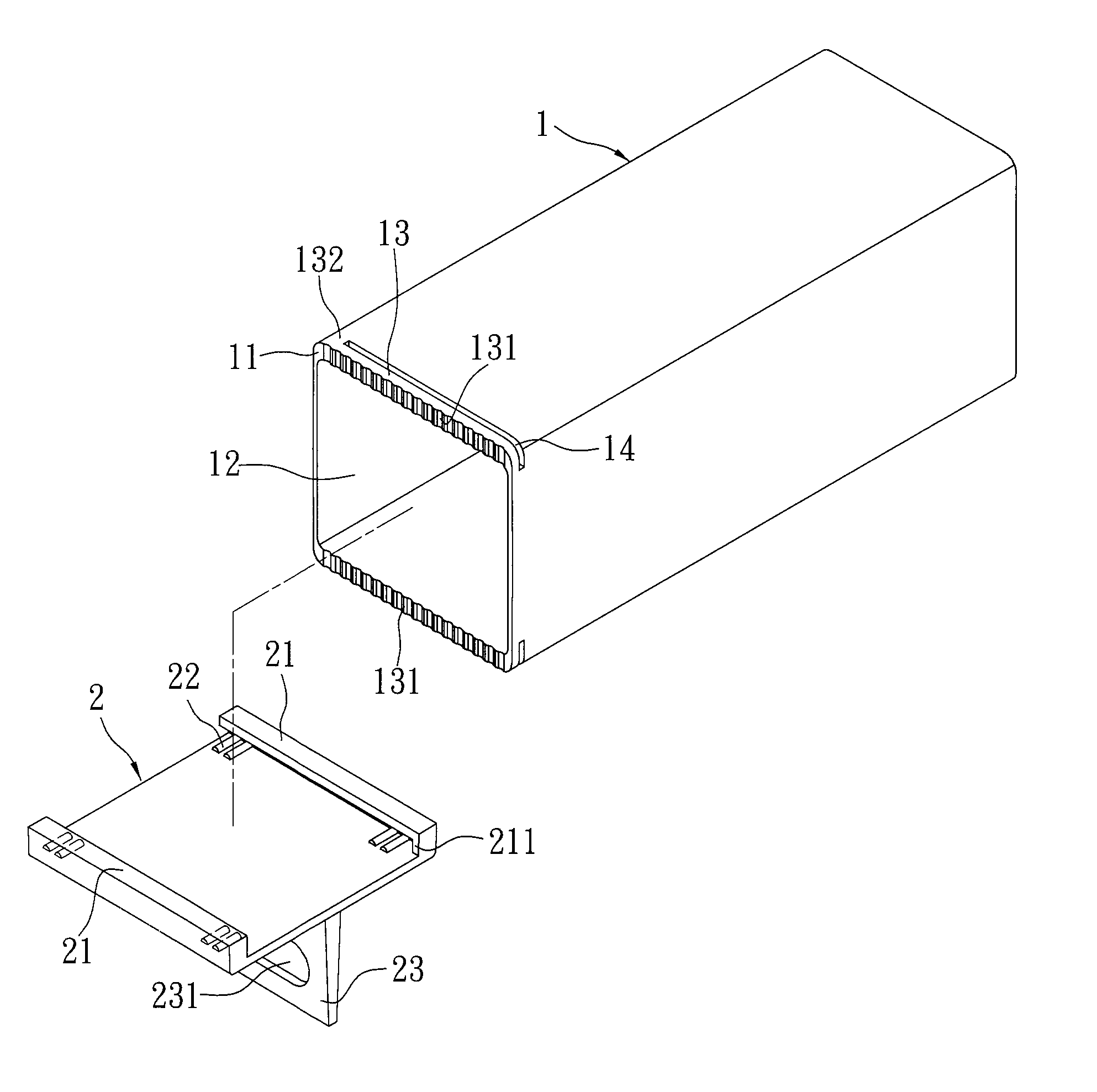
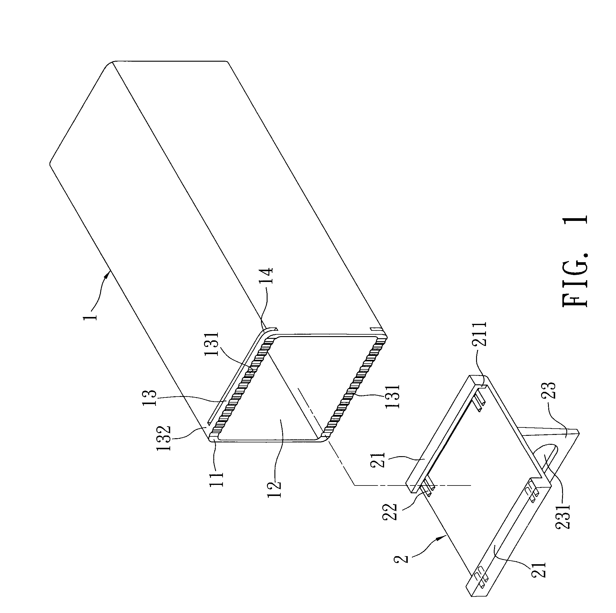
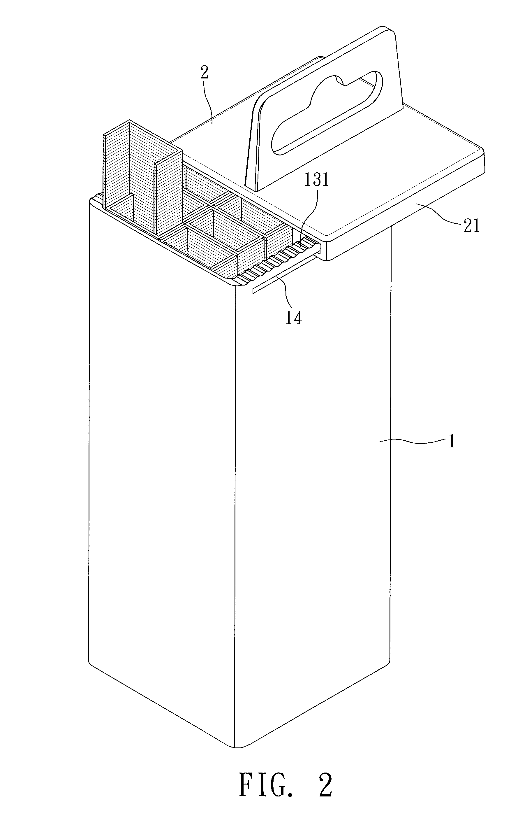
[0024]Of course, there are still many other preferred embodiments of the present invention that are different from each other in a few details. Refer to FIG. 3 that indicates the present invention, wherein an opening side 11A is defined on the receiving box 1A. The opening side 11A includes an opening and a receiving space 12A formed therein. Slide bases 13 are respectively extended from two opposite sides of the receiving box 1A near the opening side 11A. A plurality of first resisting portions 131A are raised on each of the slide bases 13A. A blocker 132A is further formed on the slide base 13A.

[0025]Slide portions 21A suitable to slide on the slide bases 13A are extended from two opposite ends of a surface of the cover body 2A. At least a second resisting portion 22A, capable of being resisted by the first resisting portion 131A, is raised from a surface of the cover body 2A opposite to the first resisting portion 131A. The second resisting portions 22A shown in the drawings are ...

first embodiment

[0029]Another resisting structure is illustrated in FIG. 7, in which each of the second resisting portions 22D of the cover body 2 is a receiving hole opposite to the first resisting portion 131. While in use, the receiving hole 22D can receive the first resisting portion 131 and resist the motion of the first resisting portion 131, thereby achieving the same effects of the

[0030]FIGS. 8 and 9 indicate a fixing structure for ensuring the cover body 2 to be fixed on the receiving box 1 when the receiving box 1 is closed. A bendable fixer 21E is extended from the bottom edge of one side of the cover body 2. The fixer 21E can be bent and stuck within the fixing aperture 11E formed on the receiving box 1 and corresponding to the fixer 21E, so as to fix the cover body 2 on the receiving box 1 effectively and prevent the cover body 2 from loosening.


PUM


Abstract

A box structure includes a receiving box with an opening side having thereon an opening and forming therein a receiving space; slide bases respectively installed on two opposite lateral sides of the receiving box 1, wherein the two opposite lateral sides are close to the opening side of the receiving box; a plurality of first resisting portions raised on the slide bases; and a cover body, wherein two opposite ends of the cover body are extended respectively to form slide portions capable of sliding on the slide bases, and at least a second resisting portion for being resisted by the first resisting portion is raised on the cover body. When being used, the slide portions of the cover body penetrate through the slide slots formed on the receiving box, and the second resisting portion is capable of moving stepwisely on the first resisting portions for opening or closing the receiving box.

Description

FIELD OF THE INVENTION[0001]The present invention relates to a box structure, and more particularly to structures respectively installed on an opening side of a receiving box and one side of a cover body, wherein both structures are capable of sliding relatively so that the receiving box can be opened or closed by a stepwise movement of the cover body and the receiving box while the cover body is mounted on the receiving box.BACKGROUND OF THE INVENTION[0002]A common receiving box structure is shown in FIG. 10. The box is formed by a cover 9 and a receiving box 8. A plurality of raised portions 81 are formed on the outer surface of the receiving box 8. On the other hand, other raised portions 91 are also formed within the inner surface of the cover 9 for being resisted by the raised portion 81. Furthermore, a slice 92 is disposed on the top surface of the cover 9, having a through hole 921 for hanging.[0003]When it is necessary to take articles out of the above-mentioned box structur...

Claims


Application Information

Patent Timeline
IPC IPC(8): B65D43/12
CPCB65D43/12B65D51/242B65D43/20
Inventor WANG, KUANG-PIN
Owner WANG KUANG PIN
Why Eureka
Try Eureka