Method and Apparatus for Carbon Dioxide Gettering for a Chip Module Assembly

a carbon dioxide and chip module technology, applied in the field of electromechanical packaging, can solve the problems of increasing manufacturing and maintenance costs, unreworkable assembled flip-chips/module substrates, and increasing the cost of manufacturing and maintenance, and achieve the effect of preventing solder joint corrosion

Inactive Publication Date: 2008-06-05
GLOBALFOUNDRIES INC
View PDF14 Cites 3 Cited by
  • Summary
  • Abstract
  • Description
  • Claims
  • Application Information

AI Technical Summary

Benefits of technology

[0015]According to the preferred embodiments of the present invention, a chip module assembly includes a CO2 getter exposed through a gas-permeable membrane to a chip cavity of a chip module. One or more chips is / are enclosed within the cavity. The CO2 getter comprises a liquid composition including 1,8-diaza-bicyclo-[5,4,0]-undec-7-ene (DBU) in a solvent that includes an alcohol, preferably, 1-hexanol. In one embodiment of the present invention, a sheet of gas-permeable membrane is heat-welded to form a pillow-shaped bag in which the liquid composition is sealed. The pillow-shaped bag containing the liquid composition is preferably disposed in a recess of a heat sink and exposed to the cavity through a passage between the recess and the cavity. The CO2 getter can remove a relatively large amount of carbon dioxide from the cavity, and thus effectively prevents solder joint corrosion. For example, based on the formula weights and densities of the DBU and 1-hexanol, 200 g of the liquid composition can remove over 34 g of carbon dioxide.

Problems solved by technology

However, as discussed below, the use of the polymeric chip underfill disadvantageously renders the assembled flip-chip(s) / module substrate un-reworkable.
Polymeric chip underfill 180 protects C4 solder joints 175 but, unfortunately, renders the assembled flip-chips 170 / module substrate 120 un-reworkable.
However, the use of polymeric chip underfill 180 stands as an obstacle to reworkablility and, thus, increases the cost of manufacturing and maintenance.
Unfortunately, C-ring seal 301 requires a larger module substrate 320 and a larger cap 360 (compared to module substrate 120 and cap 160 shown in FIG. 1) and, thus, results in the loss of precious PCB real estate (i.e., the larger footprint of module substrate 320 and cap 360 occupies a larger area on PCB 110) as well as increased manufacturing cost.
A drawback to this approach is that the MSD merely absorbs the carbon dioxide and, consequently, has a limited capacity.
This is a significant drawback because MSD has relatively low removal efficiency.

Method used


Image

  • Method and Apparatus for Carbon Dioxide Gettering for a Chip Module Assembly
  • Method and Apparatus for Carbon Dioxide Gettering for a Chip Module Assembly
  • Method and Apparatus for Carbon Dioxide Gettering for a Chip Module Assembly

Examples


Embodiment Construction

1. Overview

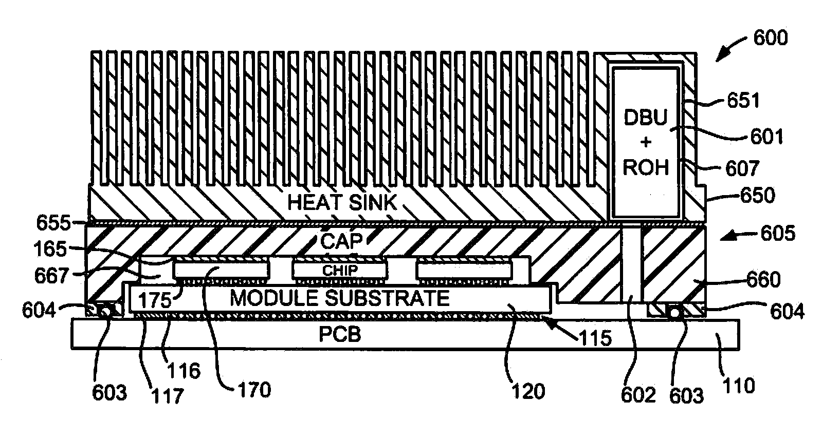
[0025]In accordance with the preferred embodiments of the present invention, a chip module assembly includes a CO2 getter exposed through a gas-permeable membrane to a chip cavity of a chip module. One or more chips is / are enclosed within the cavity. The CO2 getter comprises a liquid composition including 1,8-diaza-bicyclo-[5,4,0]-undec-7-ene (DBU) in a solvent that includes an alcohol, preferably, 1-hexanol. In one embodiment of the present invention, a sheet of gas-permeable membrane is heat-welded to form a pillow-shaped bag in which the liquid composition is sealed. The pillow-shaped bag containing the liquid composition is preferably disposed in a recess of a heat sink and exposed to the cavity through a passage between the recess and the cavity. The CO2 getter can remove a relatively large amount of carbon dioxide from the cavity, and thus effectively prevents solder joint corrosion. For example, based on the formula weights and densities of the DBU and 1-hexanol, 2...


PUM


Abstract

A chip module assembly includes a CO2 getter exposed through a gas-permeable membrane to a chip cavity of a chip module. One or more chips is / are enclosed within the cavity. The CO2 getter comprises a liquid composition including 1,8-diaza-bicyclo-[5,4,0]-undec-7-ene (DBU) in a solvent that includes an alcohol, preferably, 1-hexanol. In one embodiment, a sheet of gas-permeable membrane is heat-welded to form a pillow-shaped bag in which the liquid composition is sealed. The pillow-shaped bag containing the liquid composition is preferably disposed in a recess of a heat sink and exposed to the cavity through a passage between the recess and the cavity. The CO2 getter can remove a relatively large amount of carbon dioxide from the cavity, and thus effectively prevents solder joint corrosion. For example, based on the formula weights and densities of the DBU and 1-hexanol, 200 g of the liquid composition can remove over 34 g of carbon dioxide.

Description

[0001]This patent application is a divisional application of U.S. patent application Ser. No. 11 / 424,250 (docket no. ROC920050481US1), filed Jun. 15, 2006, entitled “METHOD AND APPARATUS FOR CARBON DIOXIDE GETTERING FOR A CHIP MODULE ASSEMBLY”, which is hereby incorporated by reference.BACKGROUND OF THE INVENTION[0002]1. Field of Invention[0003]The present invention relates in general to the field of electronic packaging. More particularly, the present invention relates to electronic packaging that provides carbon dioxide gettering for a chip module assembly.[0004]2. Background Art[0005]Electronic components, such as microprocessors and integrated circuits, are generally packaged using electronic packages (i.e., modules) that include a module substrate to which one or more electronic component(s) is / are electronically connected. A single-chip module (SCM) contains a single electronic component such as a central processor unit (CPU), memory, application-specific integrated circuit (A...

Claims


Application Information

Patent Timeline
Patent Type & Authority Applications(United States)
IPC IPC(8): H01L23/26B01D53/62
CPCH01L23/26H01L2924/1433H01L2924/15311H01L2224/16225H01L2224/73253Y02C10/04Y02C20/40
Inventor KUCZYNSKI, JOSEPH
Owner GLOBALFOUNDRIES INC
Why Eureka
Try Eureka