
Radio frequency surface acoustic wave proximity detector

a radio frequency surface and detector technology, applied in generators/motors, instruments, specific gravity measurements, etc., can solve the problems of heavy isolation hardware, heavy isolation armor and wires, and high undesirable weight-sensitive aircraft design, so as to reduce the need for heavy, complex and difficult to maintain sensors

Active Publication Date: 2008-06-05
SIMMONDS PRECISION PRODS
View PDF9 Cites 12 Cited by
  • Summary
  • Abstract
  • Description
  • Claims
  • Application Information

AI Technical Summary

Benefits of technology

[0011]The subject invention is directed to a new and useful proximity sensor that uses SAW technology with a sensing section to alleviate the need for heavy, complex and difficult to maintain sensors.

Problems solved by technology

If systems do not operate properly, the consequences can be grave.
The heavy isolation armor and wire required are highly undesirable in weight sensitive aircraft design.
One alternative is voltage sensing capacitive type sensors, which may require heavy isolation hardware due to capacitive coupled voltage due to EMI.
Magnetic or optical interrupt switches, although much lighter due to less shielding, are very failure prone in the harsh conditions of aviation.
Further, magnetic switches attract ferrous metal filings which inhibit the detection of near / far condition, resulting in false condition reporting.
Optical switches suffer from foreign object contamination, such as dirt, which again reduces the performance of the device.
Wire requires a number of aircraft interactions for installation, which drives up cost in both design and manufacturability.
Additionally, wire is heavy and difficult to troubleshoot when operation fails.
However, Zigbee devices require power not only for the necessary Zigbee controller / router devices but for the sensors as well.
Although these power requirements can be met wirelessly (e.g., sensor batteries), this approach is poorly suited to application in an aviation platform because of the associated failure rates and maintenance.
Although RFID has the capability to have a passive tag, the inductive coupling that is typically used requires close proximity and can perform below aviation standards.

Method used


Image

  • Radio frequency surface acoustic wave proximity detector
  • Radio frequency surface acoustic wave proximity detector
  • Radio frequency surface acoustic wave proximity detector

Examples


Embodiment Construction

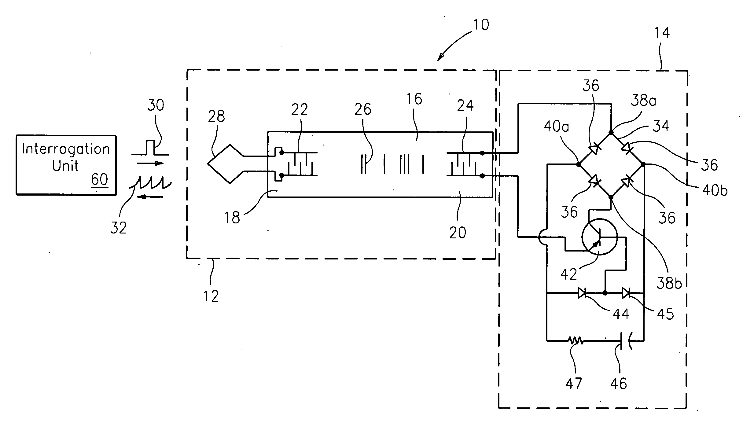
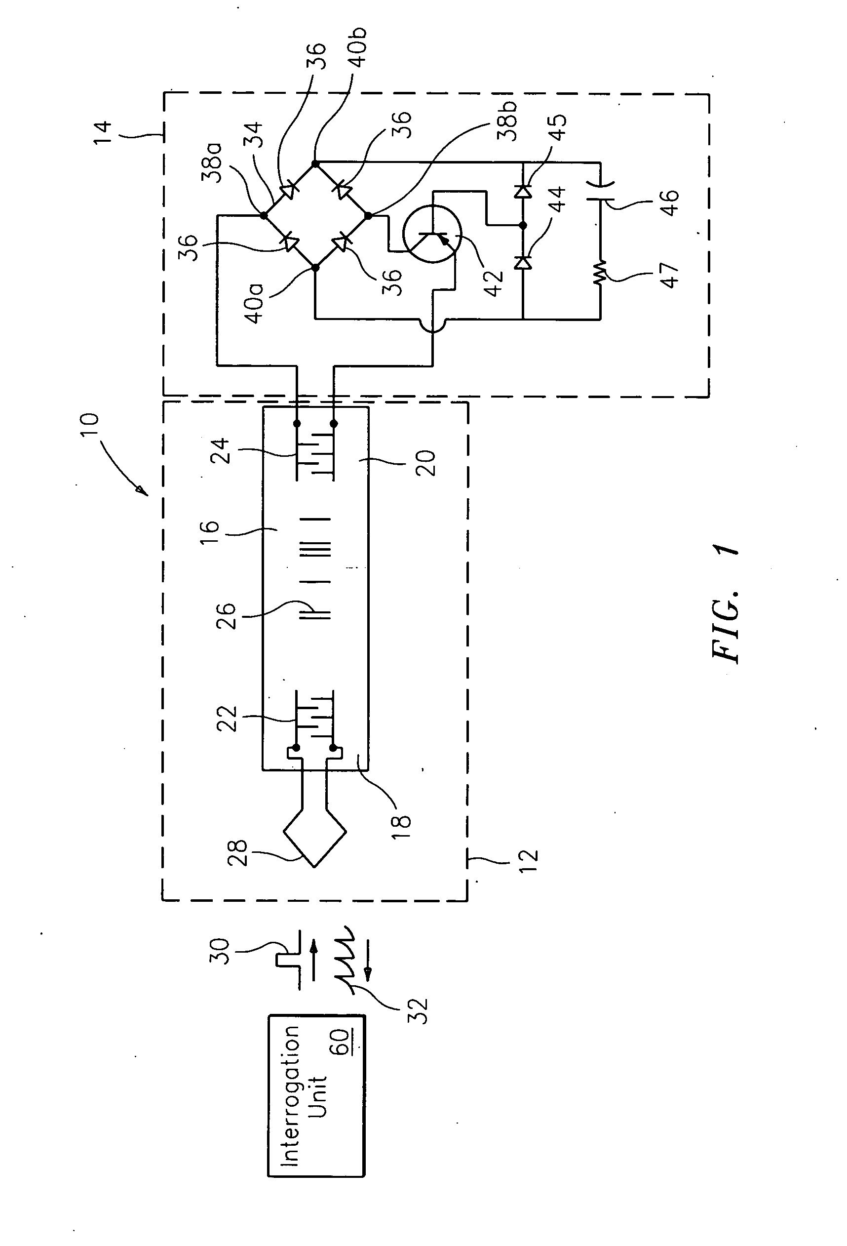
[0025]Referring now to the drawings, like reference numerals identify similar aspects or features of the proximity sensor of the subject invention. There is illustrated in FIG. 1, an exemplary embodiment of the proximity sensor contemplated by the inventor of the subject application, which is designated generally by reference numeral 10. The proximity sensor 10 includes, among other things, a SAW device 12 connected to a load or sensing section 14 for determining a position of a moving object (not shown). Generally, the proximity sensor 10 indicates that the object is in either a far field position or a near field position (e.g., open or closed, respectively). Many aviation subsystem would benefit from using the proximity sensor 10 to determine, for example, a door / hatch position, landing gear position, blade fold, weight on wheel and the like.

[0026]The proximity sensor 10 of the subject invention includes a substrate 16 for supporting a SAW as is well known. The substrate 16 has a ...


PUM


Abstract

A proximity sensor for determining a position of an object. The proximity sensor includes a SAW device having a load end and an input end for receiving an input pulse. A sensing section connects to the load end of the SAW device. When the object is in a first position, the sensing section provides a first response indicative of the first position and, when the object is in a second position, the sensing section provides a second response indicative of the second position such that the position of the object can be determined based upon the response to the input pulse.

Description

BACKGROUND OF THE INVENTION[0001]1. Field of the Invention[0002]The subject invention is related to proximity detectors, and more particularly, to an indirect proximity detector that uses surface acoustic wave (SAW) technology to reduce weight and complexity as compared to prior art sensors to meet the rigorous demands of the aviation industry.[0003]2. Description of the Related Art[0004]In aviation, mechanical subsystems are subject to very harsh conditions, so it is imperative that proper operation be verified. If systems do not operate properly, the consequences can be grave. Aircraft are subject to the Federal Aviation Regulations (FAR), which imposes very strict requirements on system performance. In terms of electrical equipment, FAR requires that equipment must be installed so that operation of any one unit or system of units will not adversely affect the simultaneous operation of any other electrical unit or system essential to the safe operation.[0005]Proximity sensors have...

Claims


Application Information

Patent Timeline
Patent Type & Authority Applications(United States)
IPC IPC(8): G01B17/00H03H9/25H10N30/00
CPCG01B17/00
Inventor BECHHOEFER, ERIC
Owner SIMMONDS PRECISION PRODS
Learn More