Non-destructive testing of physical characteristics of composite structures

a composite structure and non-destructive testing technology, applied in the direction of resistance/resistance/impedence, measurement devices, instruments, etc., can solve the problems of ineffective non-destructive testing techniques for composite structures, interference with internal stress distribution and overall performance, and disbond between cfrp materials and concr

Inactive Publication Date: 2008-06-05
UNIVERSITY OF MISSOURI
View PDF13 Cites 13 Cited by
  • Summary
  • Abstract
  • Description
  • Claims
  • Application Information

AI Technical Summary

Benefits of technology

[0012]In another aspect the invention is directed to a method for detecting an anomaly in a carbon fiber reinforced polymer material adhered to a concrete substrate comprising directing two transmitted electromagnetic wave signals from a probe to the carbon fiber reinforced polymer material, wherein a first of the two transmitted electromagnetic wave signals is polarized parallel to the preferred orientation of carbon fibers in the carbon fiber reinforced polymer material, and a second of the two transmitted electromagnetic wave signals is polarized orthogonally with respect to the first of the signals; receiving two reflected signals corresponding to said two transmitted electromagnetic signals which are orthogonally polarized; and issuing information about the composite material developed as a function of the two reflected signals.

Problems solved by technology

However, disbond between the CFRP material and the concrete can occur due to, for example, improper application, moisture, or impact damage.
Similarly, delamination within the CFRP material can interfere with internal distribution of stresses and overall performance.
Damage to concrete (for instance, impact damage) under CFRP laminates can be also critical to providing the engineering properties for which CFRP laminates are being employed because the damages of concrete under CFRP laminates are not visible through the CFRP.
Heretofore, nondestructive testing techniques have not always been effective for testing composites for conditions such as disbanding, delamination, and damage to concrete under CFRP.
However, this method is ineffective when the specimen has local surface roughness / bulging that may be smaller in spatial extent than the inspection area of the open-ended probe.
Moreover, this requires contact between a component of the test device and the specimen.
Also, its accuracy is limited by the fact that the potentiometer and waveguide probe, being distinct components, are not taking measurements simultaneously from the same location.
However, this method is ineffective when the specimen has surface roughness / bulging that may be smaller in spatial extent than the separation between the two sensing locations (about 3 inches) or when defects are not oriented.
Moreover, this method and system provides only simple subtraction of two cross-polarized reflected signals that can be useful in limited applications because interaction of the cross-polarized signals with the specimen can be different.

Method used


Image

  • Non-destructive testing of physical characteristics of composite structures
  • Non-destructive testing of physical characteristics of composite structures
  • Non-destructive testing of physical characteristics of composite structures

Examples


example 1

[0044]CFRP laminates were adhered to several cement-based samples after curing using a manual lay-up method. During the lay-up process, several intentionally disbonded regions were produced in each sample. Specimen #1 was a 380 mm by 520 mm by 90 mm mortar slab adhered with a CFRP laminate. A 60 mm by 80 mm rectangular disbonded region was produced by inserting a thin sheet of foam between the CFRP laminate and the mortar substrate. Specimen #2 was a 380 mm by 520 mm by 78 mm mortar slab with several disbonded regions produced in it by injecting air between the CFRP laminate and the mortar substrate (i.e., creating a thin airgap between CFRP and mortar). The manufactured disbonds varied in size, geometry and thickness, and ranged in area from approximately a few to several squared centimeters. Some of the disbonds also bulged up a bit creating local surface roughness that when scanned would result in standoff distance variation around it.

[0045]Specimen #1 (380×520 mm surface) was mo...

example 2

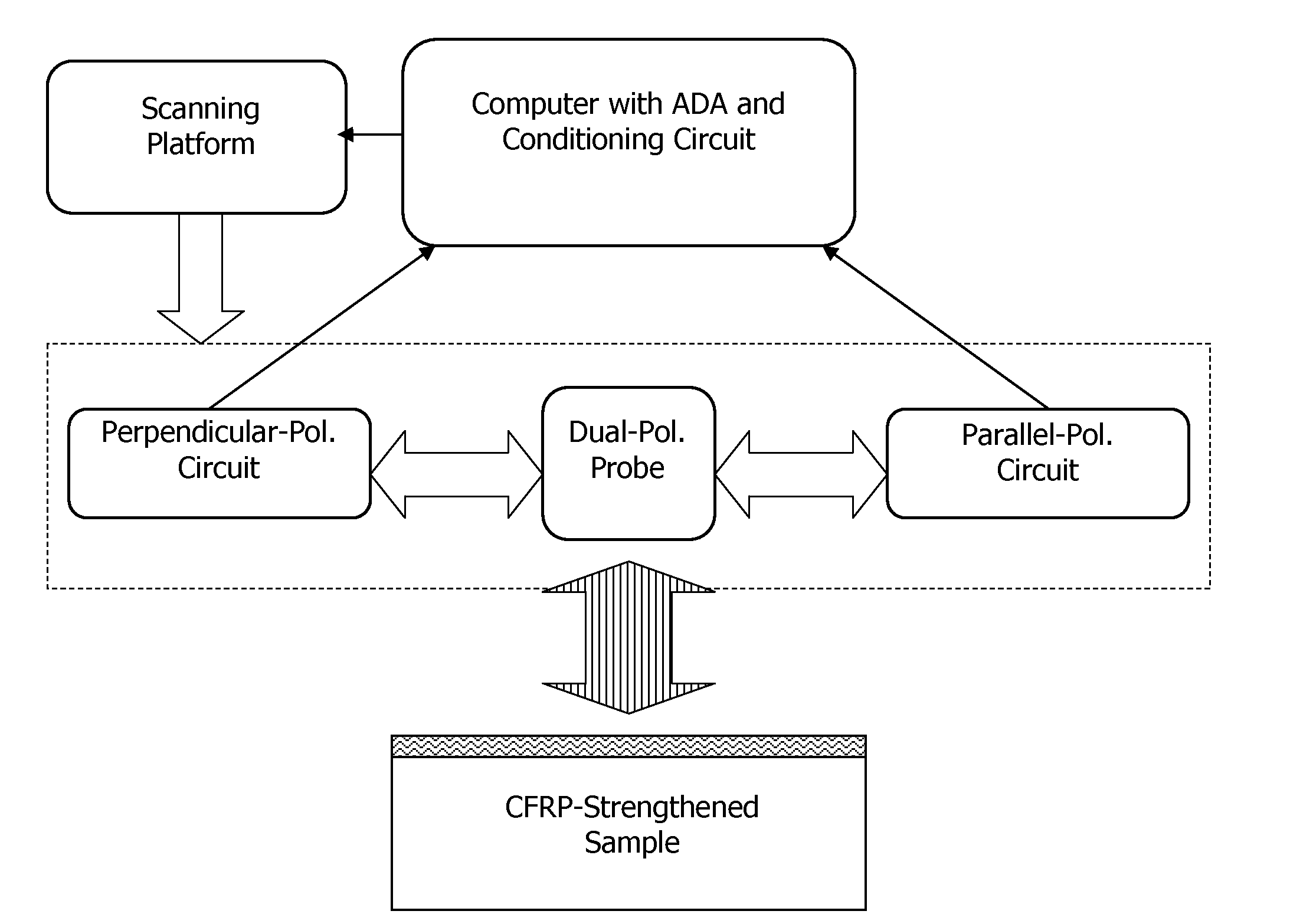
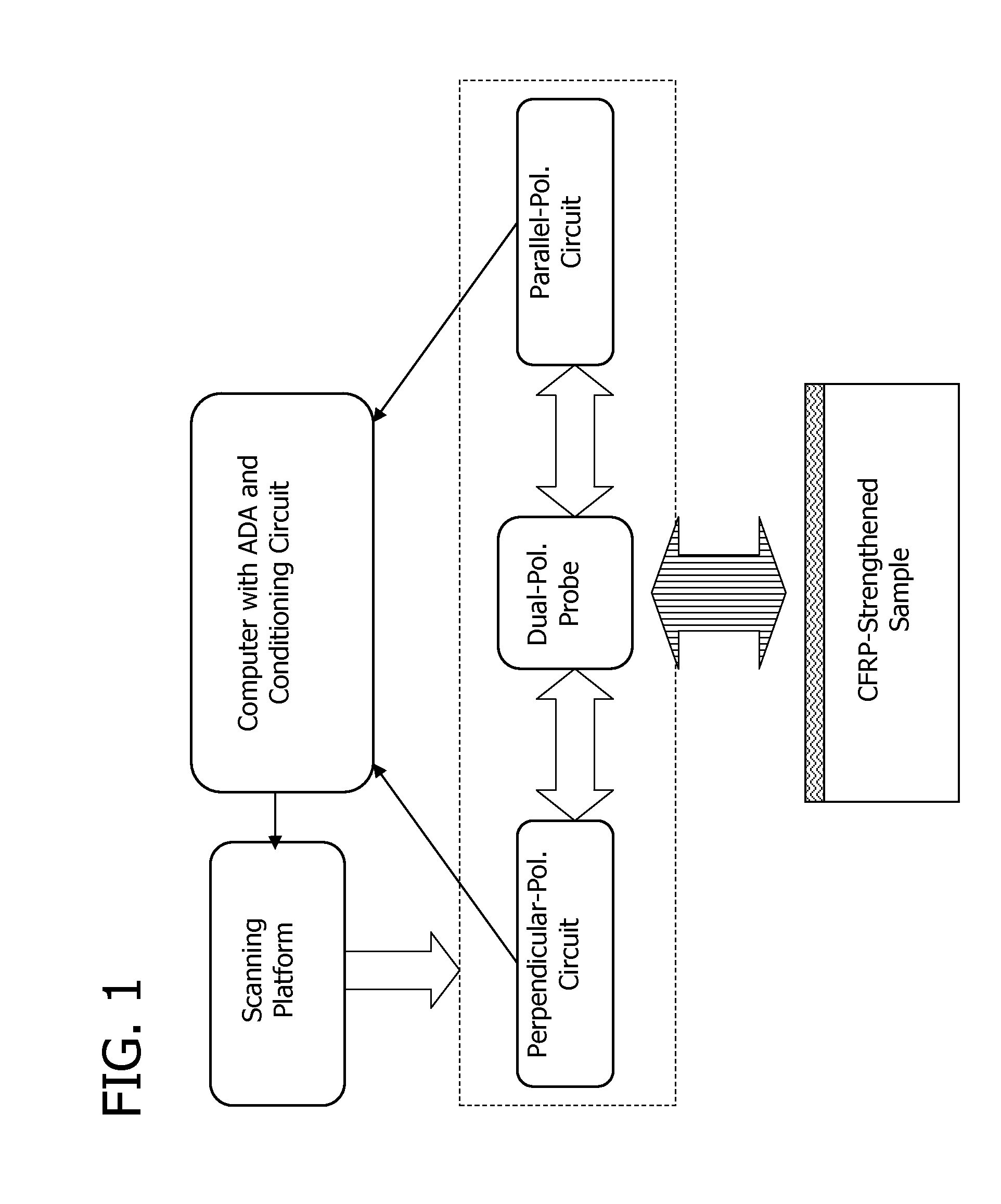
[0047]In-field inspection and monitoring of CFRP-strengthened concrete members was conducted on an actual bridge. Disbonds were intentionally introduced into CFRP patches on a bent (transverse bridge member) and on an abutment. FIGS. 11a-c show the microwave images of a 260 mm by 360 mm scanned area of the bonded CFRP patch on the bent, and FIGS. 12a-c show microwave images of a 260 mm by 320 mm scanned area of the bonded CFRP patch on the abutment. The figures show a) perpendicular polarized images, b) parallel polarized images, and c) compensated images, respectively. The results show that the image 11a from the bent patch at perpendicular polarization is more non-uniform than the image 12a of the abutment patch. This is due to the fact that the disbonds produced in the bent were thinner than the disbonds produced in the abutment, and the influence of standoff distance variation was also relatively more significant. The dark indications in the perpendicular polarization image in F...


PUM


Abstract

A method for detecting an anomaly in a composite material comprising directing two transmitted electromagnetic wave signals orthogonally polarized with respect to each other from a probe to the composite material, wherein the probe and composite material are positioned for near-field evaluation of the probe. A related apparatus comprising an open-ended square waveguide probe.

Description

FIELD OF THE INVENTION[0001]This invention is directed to a method and apparatus for nondestructive testing and evaluation of composite structures, such as complex fibrous structural materials.BACKGROUND OF THE INVENTION[0002]Composite structures comprising fibers in a matrix material have received increased attention in recent years for a wide variety of applications including commercial, civil, industrial, military, and other applications. For example, carbon fiber reinforced polymer (CFRP) materials are increasingly being used for structural applications, such as rehabilitation and upgrade of concrete structures. The invention encompasses testing of any materials comprising aligned elements such as fibers in a dielectric matrix, and is described herein with emphasis on CFRP materials for illustration purposes only.[0003]Carbon fiber reinforced polymer materials have unidirectional carbon fibers impregnated with epoxy. Such composites are externally bonded to concrete members to p...

Claims


Application Information

Patent Timeline
Patent Type & Authority Applications(United States)
IPC IPC(8): G01R27/04
CPCG01N22/02
Inventor ZOUGHI, REZAKHARKIVSKIY, SERGIYSTEPHEN, VIVIAN
Owner UNIVERSITY OF MISSOURI
Why Eureka
Try Eureka