Disk drive cage with shielding member

a technology of shielding member and drive cage, which is applied in the direction of casing/cabinet/drawer details, instruments, casings/cabinets/drawers, etc., can solve the problems of inconvenient removal and re-assembling of the shielding member, and the insufficient use of the drive cage spa

Inactive Publication Date: 2008-06-05
HON HAI PRECISION IND CO LTD
View PDF6 Cites 16 Cited by
  • Summary
  • Abstract
  • Description
  • Claims
  • Application Information

AI Technical Summary

Problems solved by technology

However, space in the drive cage is often not fully utilized.
It is inconvenient to remove a

Method used


Image

  • Disk drive cage with shielding member
  • Disk drive cage with shielding member
  • Disk drive cage with shielding member

Examples


Embodiment Construction

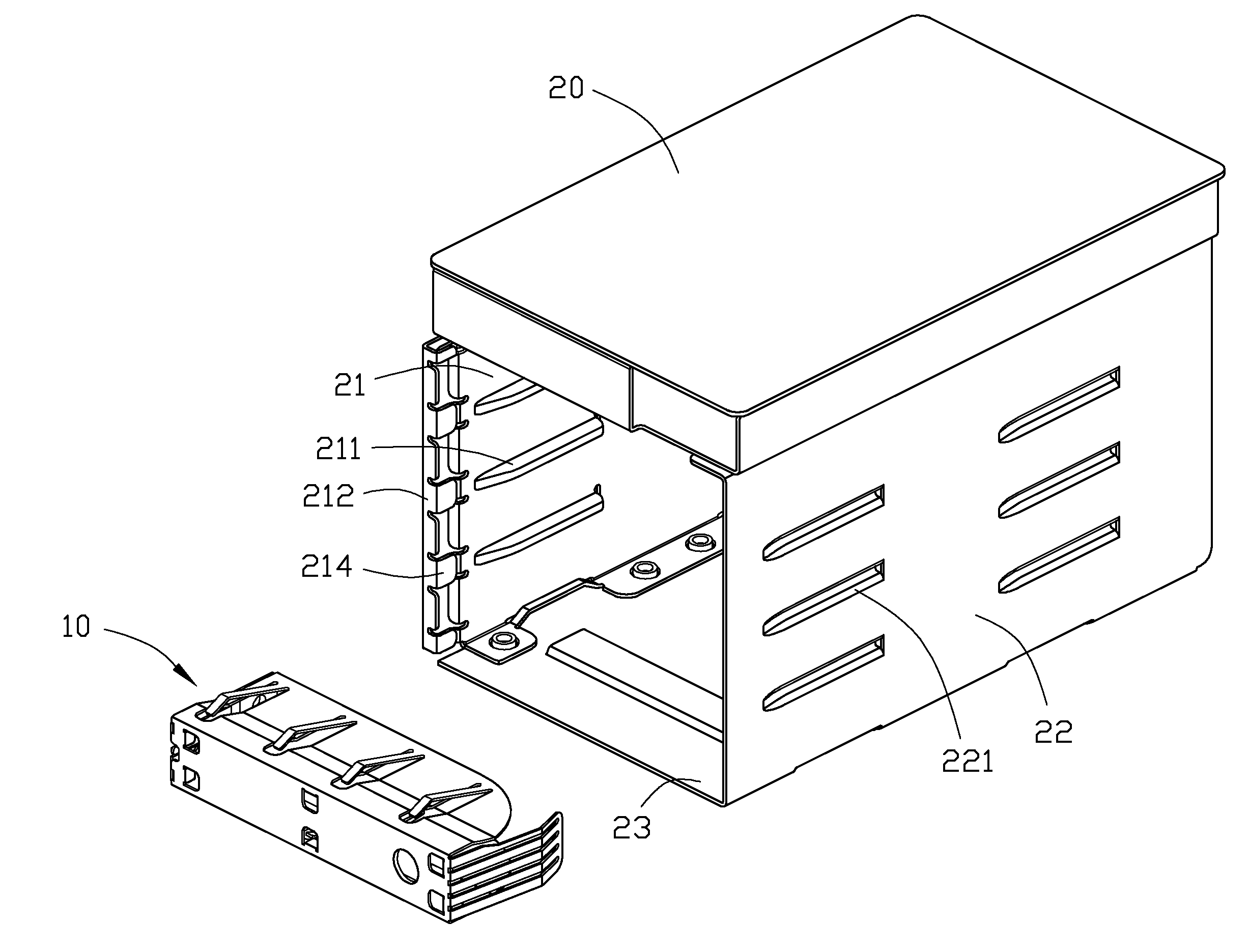
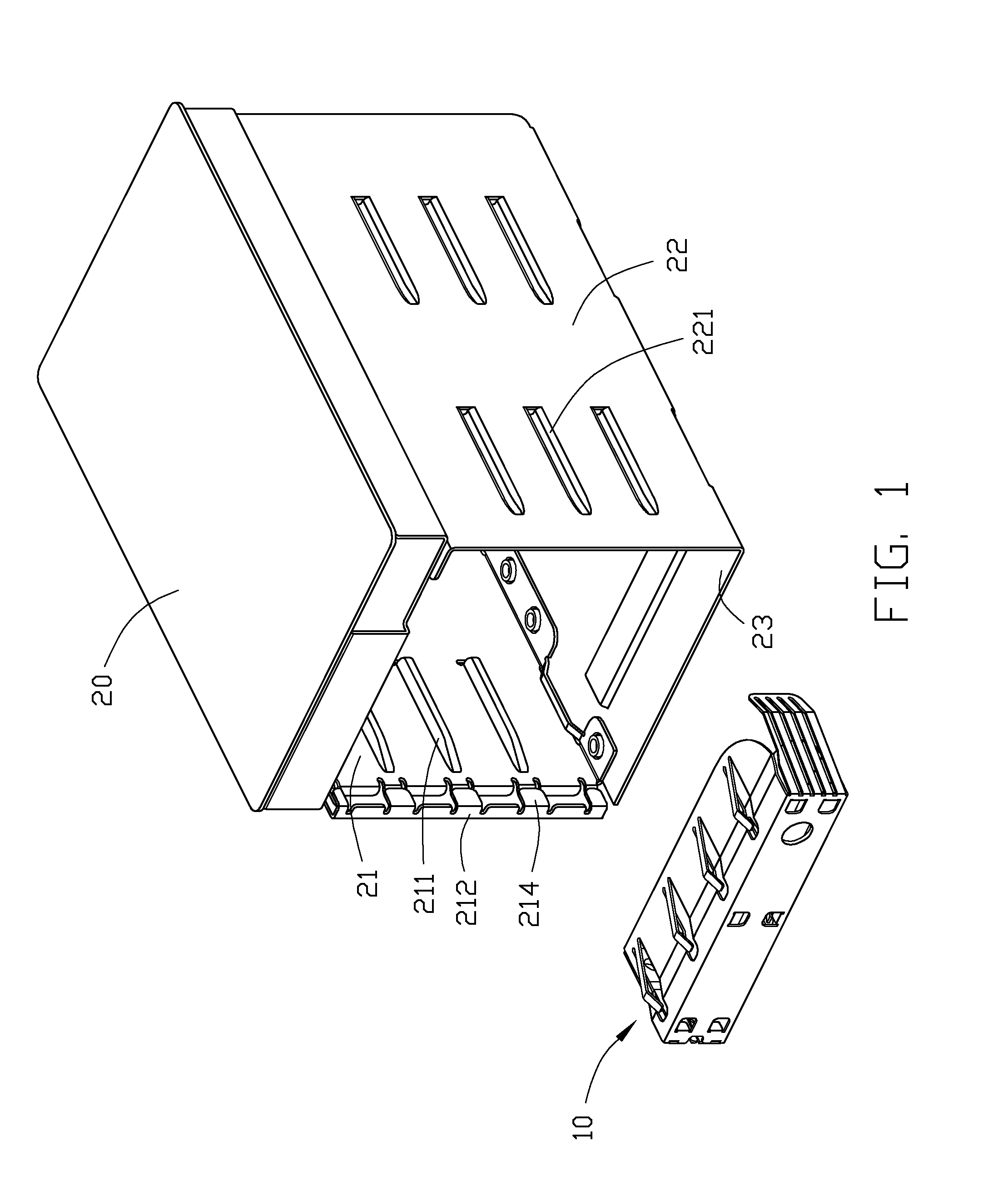
[0014]Referring to FIG. 1, a disk drive cage of a preferred embodiment of the present invention includes a bracket 20 for receiving a plurality of disk drives (not shown) therein, and a shielding member 10 for preventing EMI.

[0015]The bracket 20 is a generally rectangular shaped framework, and includes a bottom wall 23, and two parallel side plates 21, 22 respectively bent perpendicularly from two opposite side edges of the bottom wall 23. A plurality of parallel guiding pieces 211, 221 is bent in from the side plates 21, 22. A positioning flange 212 is perpendicularly bent in from a front edge of the side plate 21. A plurality of spaced bent pieces 214 is bent in from the positioning flange 212.

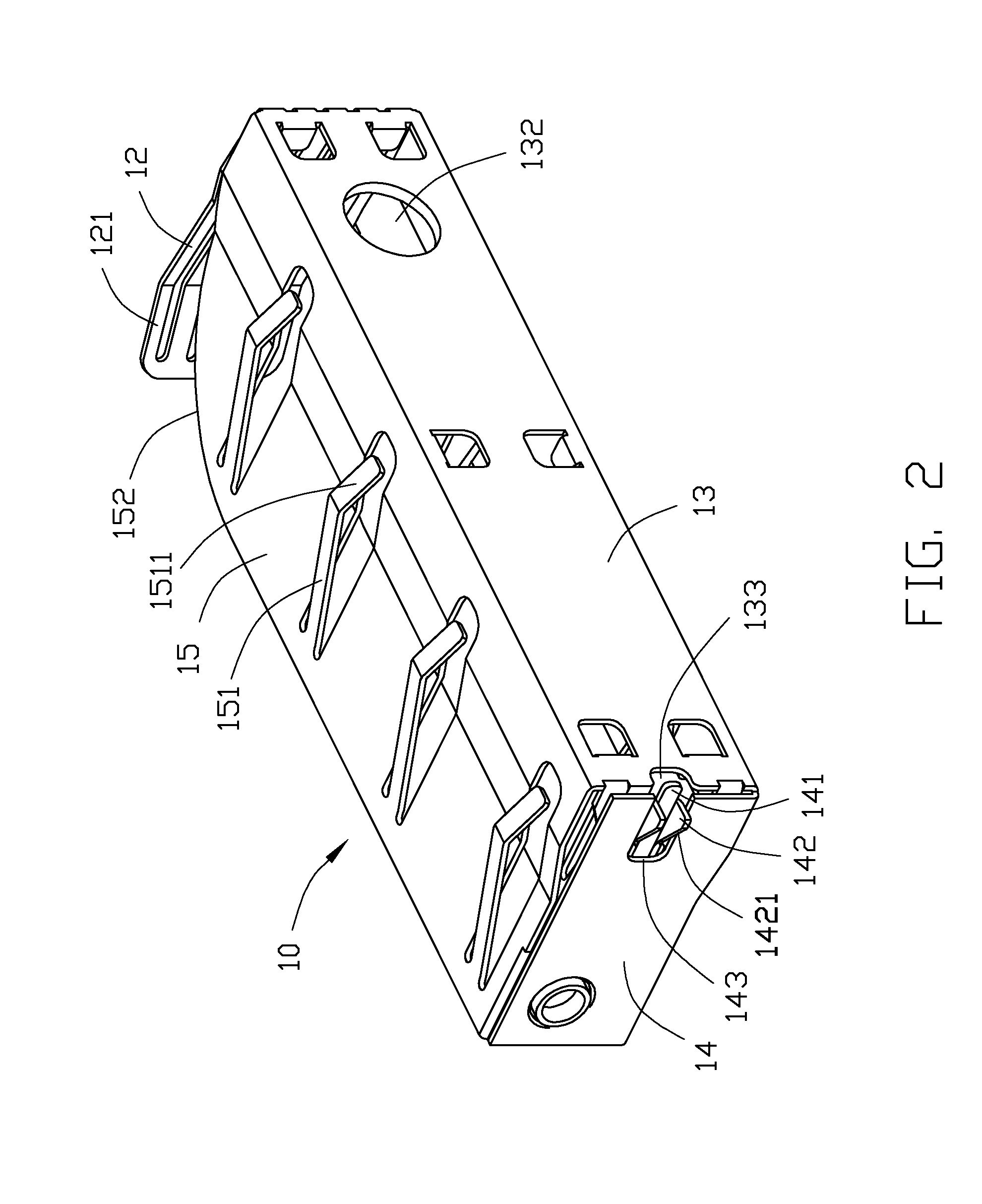
[0016]Referring to FIGS. 2 and 3, the shielding member 10 includes a front wall 13, a top wall 15, a bottom wall 16, and first and second side walls 12, 14. A circular access hole 132 is defined in a right end portion of the front wall 13. An access cutout 133 is defined in a left end edge o...


PUM


Abstract

A disk drive cage includes a bracket (20) and a shielding member (10). The bracket includes two parallel side plates (21, 22). A positioning flange (212) is bent from one of the side plates (21). The shielding member includes a front wall (13), a top wall (15), a bottom wall (16), a first side wall (12), and a second side wall (14). A resilient lip piece (141) is formed on the second side wall and having at least one locking tab (142) engaging with the positioning flange when the shielding member inserts into the bracket. The top wall and the bottom wall has arc-shaped edges (152, 162) to allow resilient deformation of the first side wall towards the arc-shaped edges by the other one of the side plates (22), and the shielding member rotating out from the bracket.

Description

BACKGROUND[0001]1. Technical Field[0002]The present invention relates to disk drive cages, and more particularly to a disk drive cage with a shielding member for preventing EMI (Electro Magnetic Interference).[0003]2. General Background[0004]In a computer or a server, a drive cage is provided to receive disk drives. However, space in the drive cage is often not fully utilized. A void is thus formed that may allow EMI to radiate therefrom. So, a shielding member is needed to cover the void. In some computer, the shielding member is usually secured to the bracket with screws or directly formed on the bracket by stamping. It is inconvenient to remove and reassemble the shielding member when the void is used to receive additional disk drives.[0005]What is needed, therefore, is a disk drive cage having a shielding member, which is conveniently assembled and removed.SUMMARY[0006]A disk drive cage includes a bracket and a shielding member. The bracket includes two parallel side plates. A p...

Claims


Application Information

Patent Timeline
IPC IPC(8): H05K5/02H05K9/00
CPCG06F1/187G11B33/125H05K9/0016G11B33/1493G11B33/128
Inventor TSAI, LUNG-SHENGCHOU, YI-LUNGCHEN, LI-PINGCHEN, WEN-TZU
Owner HON HAI PRECISION IND CO LTD
Why Eureka
Try Eureka