Travel forecasting and allocating system and method

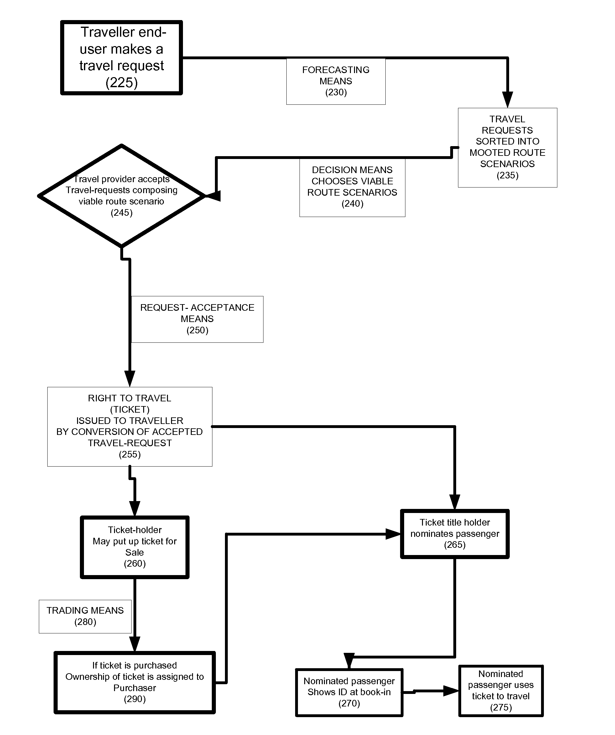
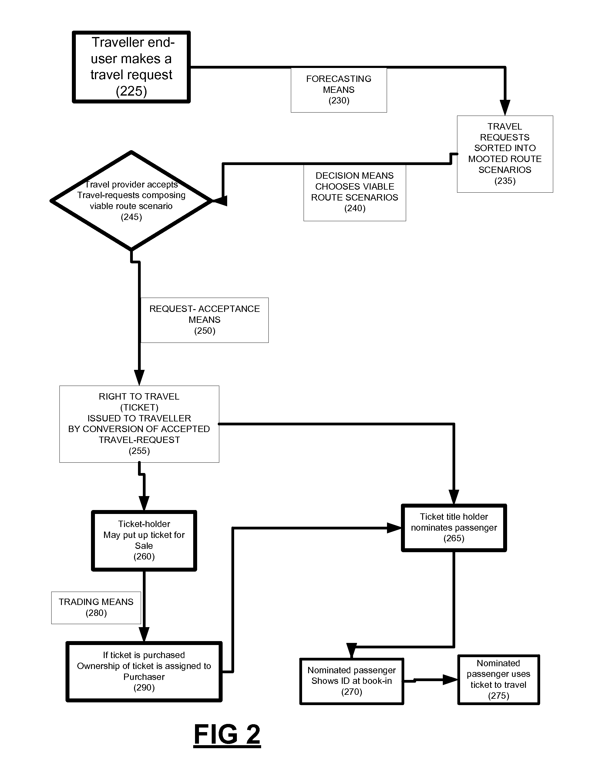
a technology of applied in the field of travel forecasting and allocating system and method, can solve the problems of inefficient matching of physical supply and demand, travellers needing to wait for transport and possibly also for other travellers, and not sure when the journey will take, so as to reduce the risk of loss to an airline caused by incorrect forecasting, efficient allocation of traveller, and minimising the risk of not using

Inactive Publication Date: 2008-06-05
BIRCH GRANT DAVON +1
View PDF42 Cites 19 Cited by
  • Summary
  • Abstract
  • Description
  • Claims
  • Application Information

AI Technical Summary

Benefits of technology

[0040]An object of the present invention is to provide a device and method that creates sufficient committed traveller demand far enough into the future to allow an airline to plan its operations to meet the demand; rather than the airline selling journey places on already scheduled travel supply which was based on forecasting.
[0041]Achieving this object removes the previously critical need for the airline to forecast that traveller demand. It is a considerable advantage of the present invention to the airline industry that the risk of losses to an airline caused by incorrect forecasting is then dissipated or lowered.
[0042]Furthermore it is an advantage in certain embodiments of the present invention to travellers that they may be able to harness and employ traveller rights wh

Problems solved by technology

Model 1 can efficiently match physical supply and demand, yet the disadvantages are that both the transport and travellers must wait for more travellers and are not sure when the journey will take place.
Model 2 is effective for both the transport and passengers in that they are certain of the journey time, yet it can be an inefficient way of matching physical supply and demand.
If the queue is larger than the transport, then it is an efficient and fair way of matching physical supply and demand, but the disadvantages are that travellers need to wait for transport and possibly also wait for other travellers.
Ad hoc charter of flights or ordering a personal taxi follow this way and are generally a more e

Method used


Image

  • Travel forecasting and allocating system and method
  • Travel forecasting and allocating system and method
  • Travel forecasting and allocating system and method

Examples


Embodiment Construction

A first example of the present invention and method of use is now described in the following detailed description.

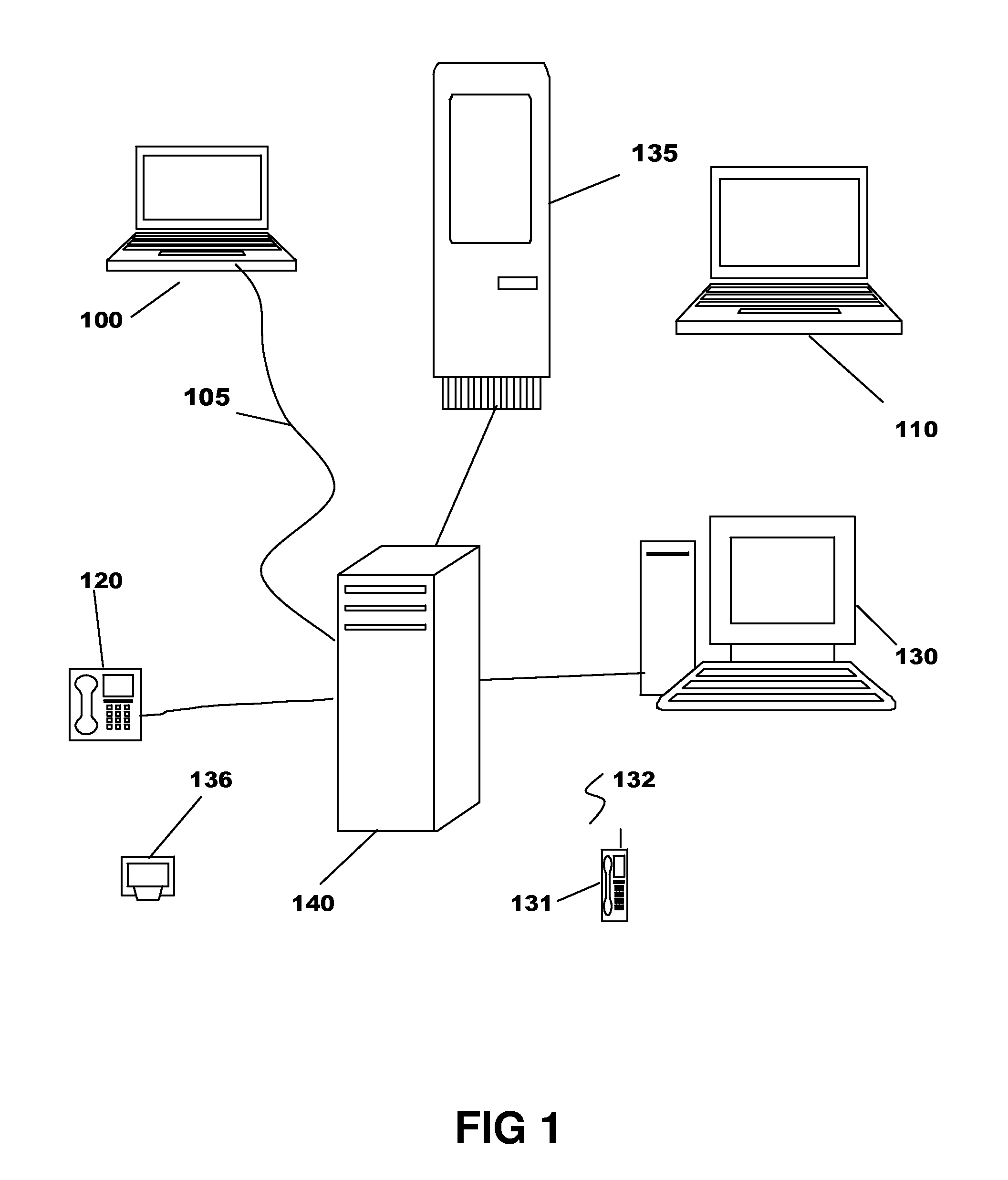
[0111]Refer now to FIG. 1 which illustrates an example of the hardware of the invention, wherein many computers of different variety are shown. Each type of computer or computer terminal may be used in this example.

[0112]FIG. 1 illustrates types of computers and computer terminals, including computing devices such as a wired laptop computer 100, a wireless laptop computer 110, a landline telephone 120, a desktop personal computer 130, a computing mobile cell phone 131, a palm top computer 136, and a computing kiosk 135 (similar to that of an automatic teller machine but which is accessible to travellers), which are connected to each other via interconnected web servers by an internet or intranet, one of which is shown as a master server 140 which hosts software, including a database management system and a website, for the invention.

[0113]These computers are characterise...


PUM


Abstract

A travel forecast and allocation computing system and method for prospective and other travel purchasers to access for requesting, receiving, and re-allocating rights to travel on passenger transportation vehicles, whereby a travel purchaser may have an opportunity of re-allocating its purchased right to travel to one or another of travel purchasers by trading it, and whereby a travel provider may have an opportunity of efficiently allocating transport to service binding travel requests and have further opportunity of relief from providing changes to reservations. The present invention makes possible economic incentive for travellers to forecast their own travel behaviour, and enable economic incentive for travellers to commit far into the future to specific travel so that airlines need not rely on their own forecasting of demand to plan their operations.

Description

CROSS REFERENCE TO RELATED APPLICATIONS[0001]This specification is related to a priority provisional patent application 2006906767 titled ‘Travel forecasting and allocation system and method’ filed in the Commonwealth of Australia on 5 Dec. 2006 by G. D. Birch.FEDERALLY SPONSORED RESEARCH[0002]Not applicableSOFTWARE PROGRAM[0003]Not applicableBACKGROUND OF THE INVENTION[0004]1. Field of Invention[0005]This invention generally relates to a business method of using a network of computers to create and allocate or otherwise dispose of travel forecasts, travel requests, and travel inventory, particularly by using the internet for passenger airline travel.[0006]2. Prior Art[0007]Scheduled airlines need to forecast travel demand in the future to plan their operations. Scheduled airlines firstly forecast travel demand, secondly allocate resources in the form of scheduled flights to supply the forecasted demand, and thirdly sell reservations on the flights. By forecasting in this manner, th...

Claims


Application Information

Patent Timeline
IPC IPC(8): G06Q10/00
CPCG06Q30/0603G06Q10/02
Inventor BIRCH, GRANT DAVONSCHUBOTZ, SHAWN IVOR
Owner BIRCH GRANT DAVON
Why Eureka
Try Eureka