
Driving shoes

a technology for driving shoes and shoes, applied in the field of shoes, can solve the problems of increasing fatigue, affecting the driving comfort, and difficult to drive a car with a general outdoor-use shoe, and achieve the effects of convenient step-change operations, stable depressing operation, and convenient carrying out of comfortable driving

Inactive Publication Date: 2008-06-12
SUZUKI FUJINORI
View PDF11 Cites 21 Cited by
  • Summary
  • Abstract
  • Description
  • Claims
  • Application Information

AI Technical Summary

Benefits of technology

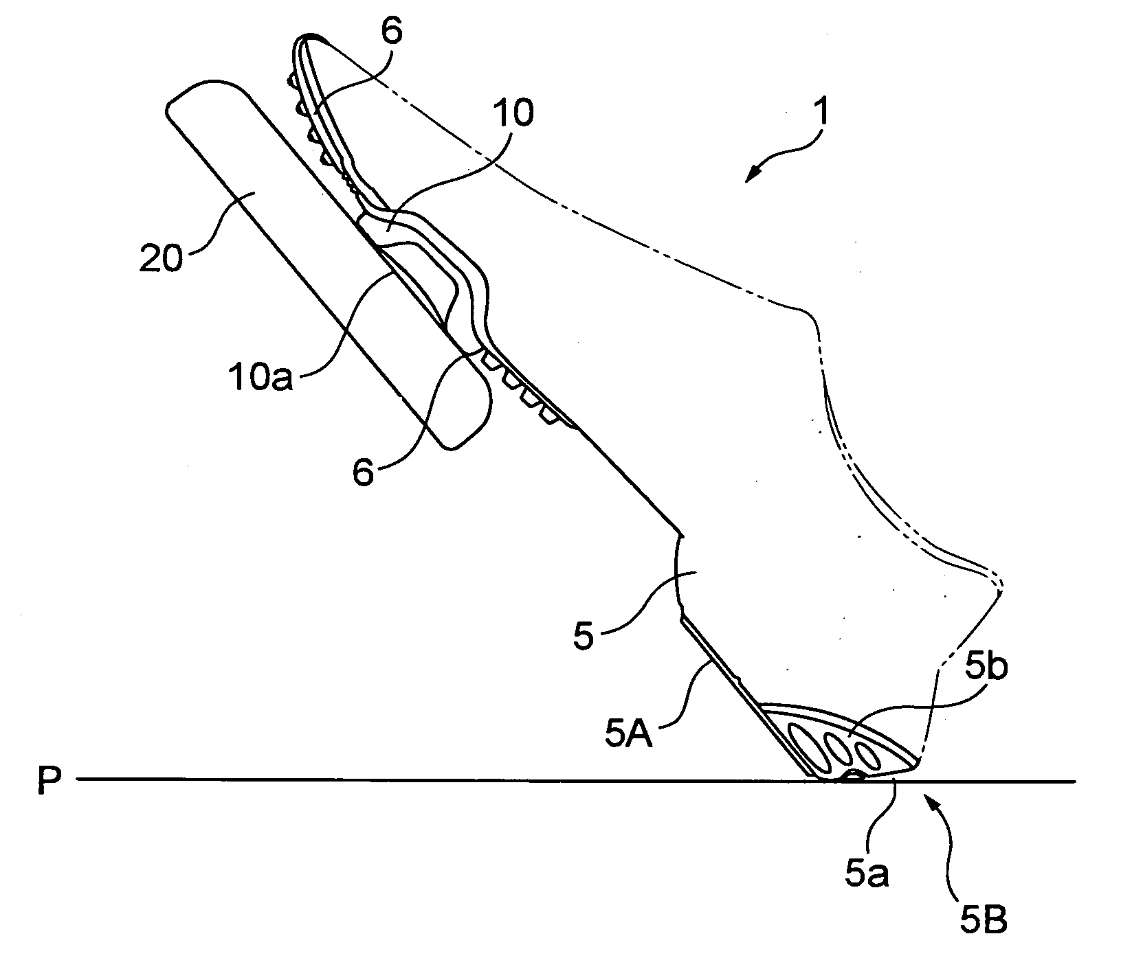
[0007]According to the above-mentioned structure, forming the inclined face increasing gradually toward a rear side formed in a side view enables a toe to be floated in a stable condition when a foot sole (shoe sole) is transferred to the accelerator pedal or the brake pedal, which allows a stable depressing operation. Furthermore, this inclined face further comprises the first face capable of coming in contact with the car floor formed outside in a width direction when depressing the accelerator pedal and the second face which is different from the face conditions of that of the first face, capable of coming in contact with the car floor formed inside in a width direction when depressing the brake pedal, which enables easy step-change operations of the accelerator pedal and brake pedal by pivoting a toe side on the heel part (as much as possible without moving the heel part).
[0008]According to the shoe for driving a car of the present invention, a shoe for driving a car is provided in which both the accelerator pedal and brake pedal can be operated stably and comfortable driving can be carried out.

Problems solved by technology

In this case, it is often difficult to drive a car with a general outdoor-use shoe as it is.
For example, a high-heeled leather shoe, a high heel, or a sandal or the like has a structure whose heel's shape is not suitable for driving a car with the shoe as it is, and therefore, a heel part is caught on the car floor, which may interfere with a step-change operation of an accelerator pedal or a brake pedal during driving.
Furthermore, particularly a high heel having a small cross section and a high heel is unstable when operating an accelerator pedal and a brake pedal, causing fatigue to increase.
Furthermore, in case of driving a car for a long time, it is easy to get stuffy in a shoe, which may interfere with comfortable driving.

Method used


Image

  • Driving shoes
  • Driving shoes
  • Driving shoes

Examples


Embodiment Construction

[0019]The embodiments of the shoe for driving a car (hereinafter referred to as a driving shoe) according to the present invention are hereinafter described with reference to the accompanying drawings.

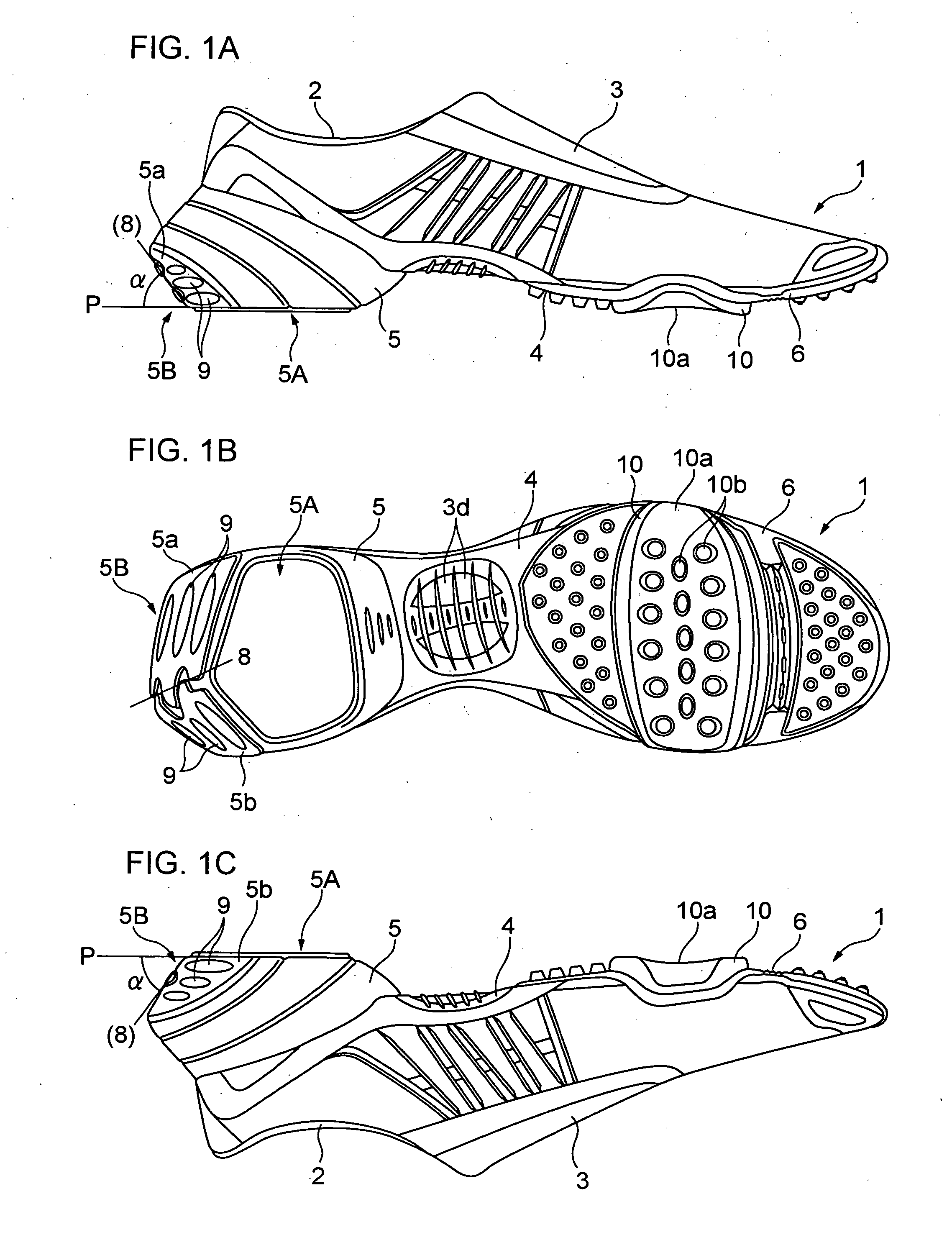
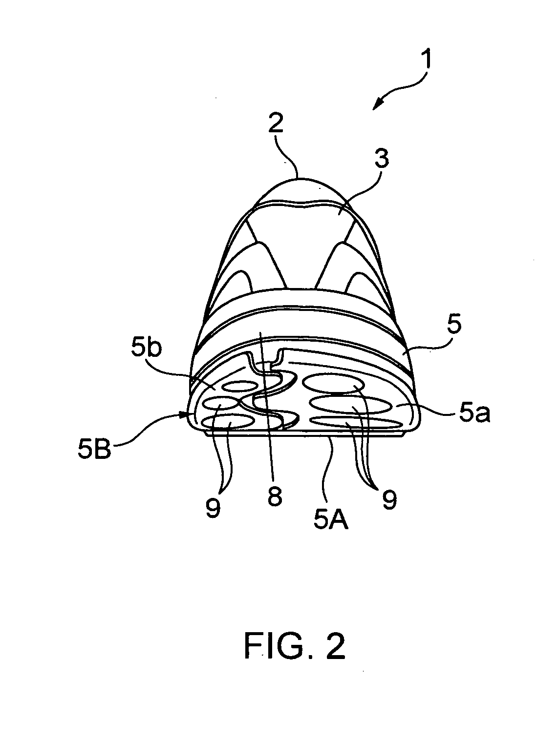
[0020]FIGS. 1A to 1C are views showing the overall structure of a driving shoe which is worn on a right foot, FIG. 1A is a side view viewed from the outside in a width direction, FIG. 1B is a bottom view, FIG. 1C is a side view viewed from the inside in a width direction, and FIG. 2 a view viewed from the rear side.

[0021]A driving shoe 1 according to the present embodiment, which has a structure to store the part lower than a driver's right ankle comprises a main body 3 provided with an opening 2 from which a leg part is inserted and a shoe sole 4 which is attached to the bottom side of the main body 3.

[0022]The above-mentioned main body 3 is a part to cover an instep of a right foot and preferably comprises a breathable material, and possibly, for example, nylon having a plenty of mes...


PUM


Abstract

A shoe for driving a car according to one aspect of the present invention comprises a heel part 5 on a foot sole 4 and an inclined face 5B increasing gradually toward a rear side in a side view. This inclined face 5B comprises a first face part 5a which is formed outside in a width direction and is capable of coming in contact with a car floor when depressing an accelerator pedal and a second face part 5b unlike the face condition of the above-mentioned first face part, which is formed inside in a width direction and is capable of coming in contact with a car floor when depressing a brake pedal.

Description

[0001]The present disclosure relates to subject matter contained in Japan Patent Application No. 2006-330468 filed on Dec. 7, 2006, which is expressly incorporated herein by reference in its entirety.BACKGROUND OF THE INVENTION[0002]The present invention relates to a shoe suitable for driving a car. When driving a car, a driver usually depresses an accelerator pedal and a brake pedal alternately with the right foot. In this case, it is often difficult to drive a car with a general outdoor-use shoe as it is. For example, a high-heeled leather shoe, a high heel, or a sandal or the like has a structure whose heel's shape is not suitable for driving a car with the shoe as it is, and therefore, a heel part is caught on the car floor, which may interfere with a step-change operation of an accelerator pedal or a brake pedal during driving. Furthermore, particularly a high heel having a small cross section and a high heel is unstable when operating an accelerator pedal and a brake pedal, ca...

Claims


Application Information

Patent Timeline
IPC IPC(8): A43B5/00
CPCA43B5/007A43B23/30A43B21/24
Inventor SUZUKI, FUJINORI
Owner SUZUKI FUJINORI
Learn More