Exterior building panel

a technology for exterior buildings and panels, applied in building roofs, building repairs, parking lots, etc., can solve problems such as inconsistent system performance of known systems

Inactive Publication Date: 2008-06-12
THE CARVIST CORP
View PDF36 Cites 46 Cited by
  • Summary
  • Abstract
  • Description
  • Claims
  • Application Information

AI Technical Summary

Benefits of technology

The present invention provides an exterior building panel with a condensation drain system. The system includes an upper reservoir and a lower chamber with a drain port for draining condensation. The wicking material in the reservoir port blocks the upward flow of exterior moisture. The technical effect of this invention is to prevent moisture from accumulating in the lower chamber and causing damage to the building structure.

Problems solved by technology

The technical problem addressed in this patent text is the need to prevent moisture from accumulating within exterior building panels caused by temperature and pressure differentials caused by varying weather conditions. Various systems have been used to try to eliminate the condensed moisture, but they may fail or prevent the drainage of the condensed moisture during sustained high wind conditions.

Method used


Image

  • Exterior building panel
  • Exterior building panel
  • Exterior building panel

Examples


Embodiment Construction

[0025]The following description and the accompanying drawings illustrate exemplary embodiments of an exterior building panel in accordance with the present invention. The description and drawings are intended to be illustrative of the inventions defined in the appended claims. In the drawings, like numerals refer to like parts throughout.

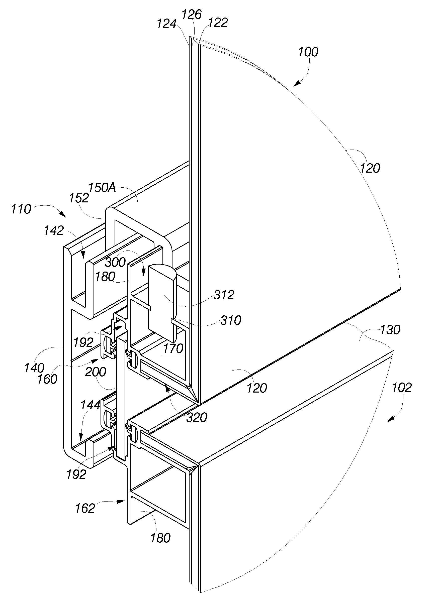
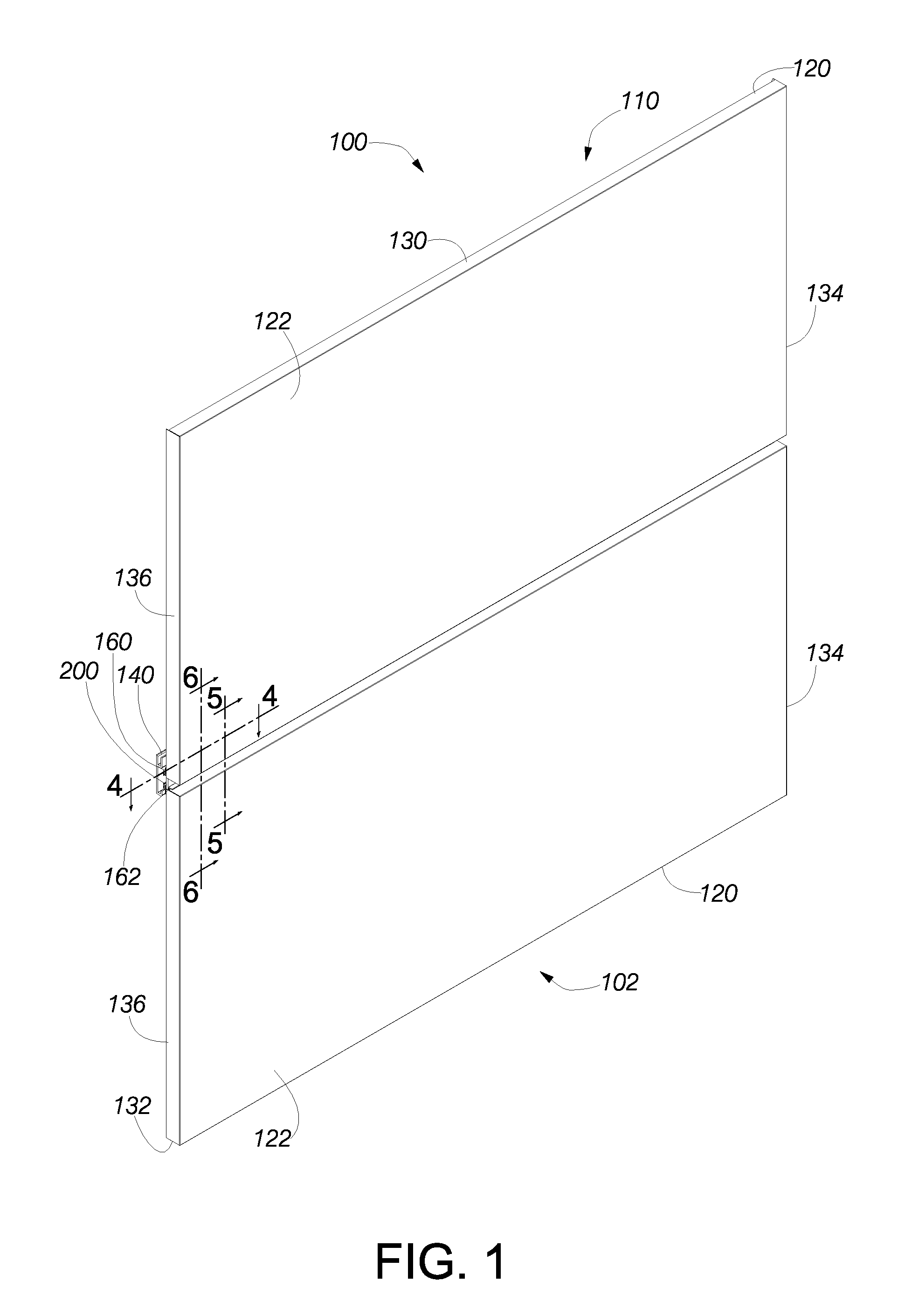
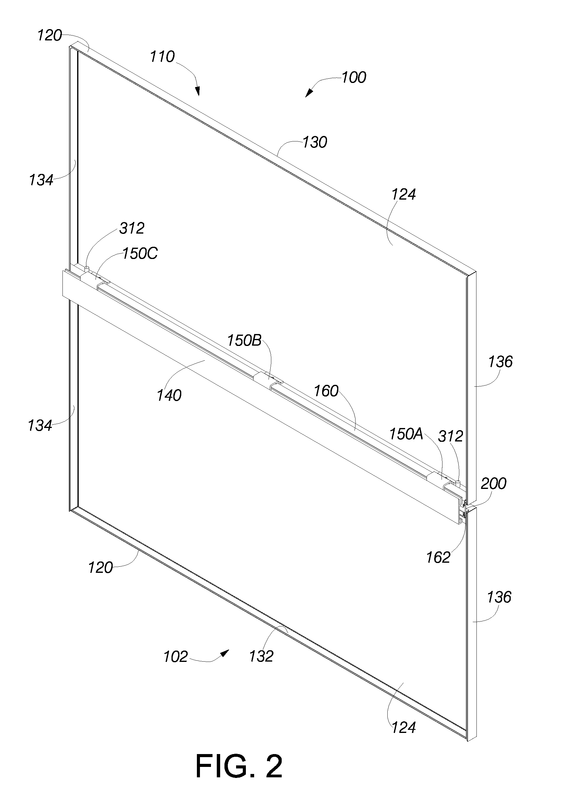
[0026]FIG. 1 illustrates a perspective view of a portion of an exterior wall of a building (not shown) showing the outsides of a first exterior wall panel 100 and a second exterior wall panel 102, wherein the second wall panel 102 is positioned below the first wall panel 100. A building advantageously includes additional panels vertically above the two panels and horizontally on either or both sides of the two panels. FIG. 2 illustrates a perspective view of the two wall panels 100, 102 looking from the interior of the building. FIG. 3 illustrates a rear elevational view of the interiors of the two wall panels 100, 102.

[0027]As illustrated in FIGS. ...


PUM


Abstract

A building panel subject to interior condensation of moisture and exterior wind-driven moisture includes a sheet having an inner surface onto which condensed moisture forms. An open upper reservoir is positioned proximate a bottom portion of the inner surface of the sheet to receive the condensed moisture. A lower chamber having at least one drain port is positioned below the upper reservoir. A wicking port connects the upper reservoir to the lower chamber. The wicking port weeps the condensed moisture from the upper reservoir to the lower chamber to drain the upper reservoir. The condensed moisture drains from the lower chamber via the drain port. The wicking port blocks the upward flow of wind-driven moisture that enters the lower chamber via the drain port.

Description


Claims


Application Information

Patent Timeline
Owner THE CARVIST CORP
Why Eureka
Try Eureka