Ball screw device having lubricating device

a technology of lubricating device and ball screw, which is applied in the direction of gear lubrication/cooling, toothed gearings, gearings, etc., to achieve the effect of effective and easy lubrication of balls, great rotational speed and convenient rotation

Inactive Publication Date: 2008-06-12
HIWIN TECH
View PDF5 Cites 8 Cited by
  • Summary
  • Abstract
  • Description
  • Claims
  • Application Information

AI Technical Summary

Benefits of technology

[0010]The primary objective of the present invention is to provide a ball screw device including a lubricating device or structure for effectively and easily lubricating the balls or the bearing members, and for facilitating the rotational movement of the ball nut and the screw shaft relative to each other in great rotational speeds.

Problems solved by technology

However, the oil is simply filled into the annular gap of the outer ball race, but may not be forced into the endless ball train guiding passage of the ball nut that is provided for receiving the balls or bearing devices.

Method used


Image

  • Ball screw device having lubricating device
  • Ball screw device having lubricating device
  • Ball screw device having lubricating device

Examples


Embodiment Construction

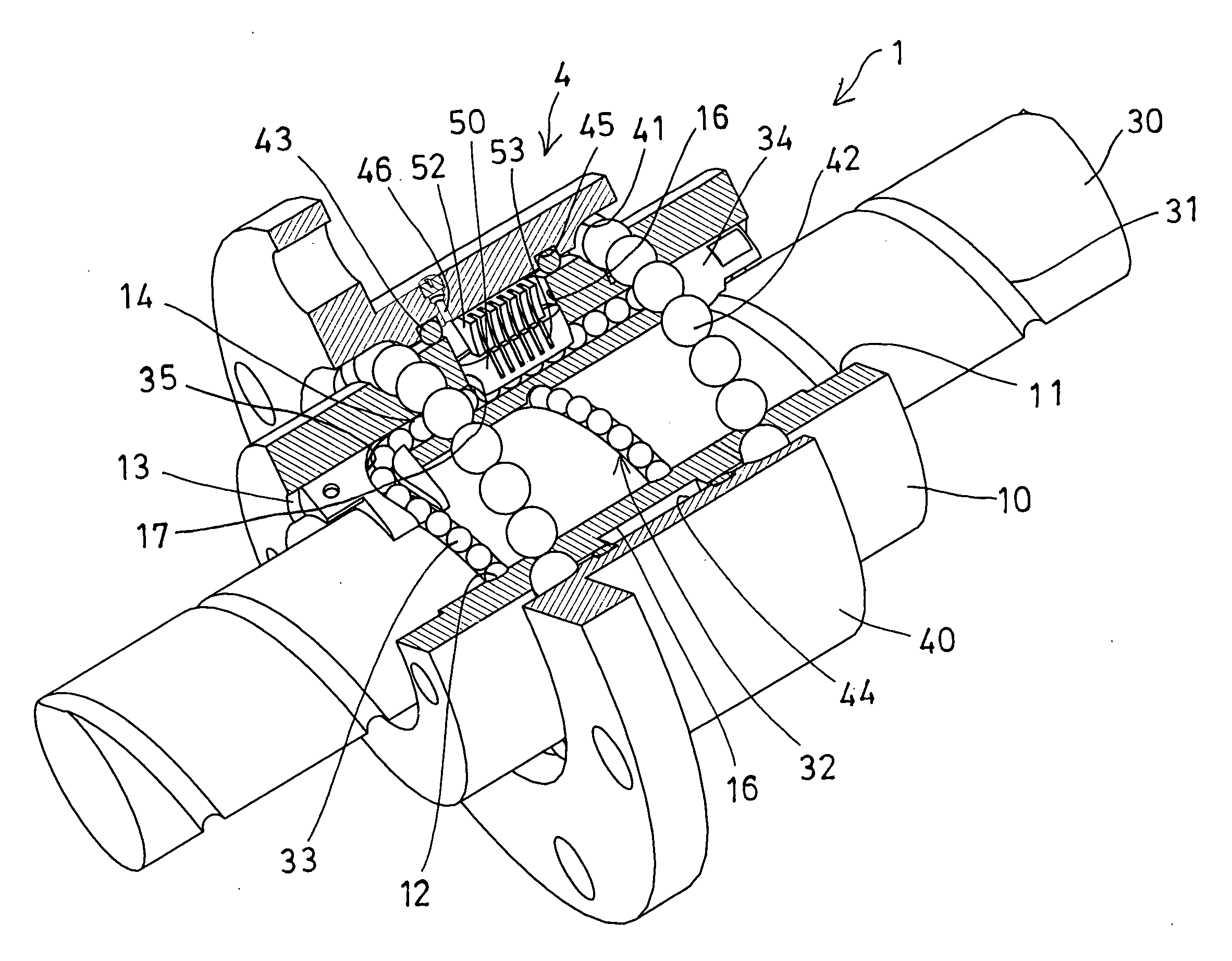
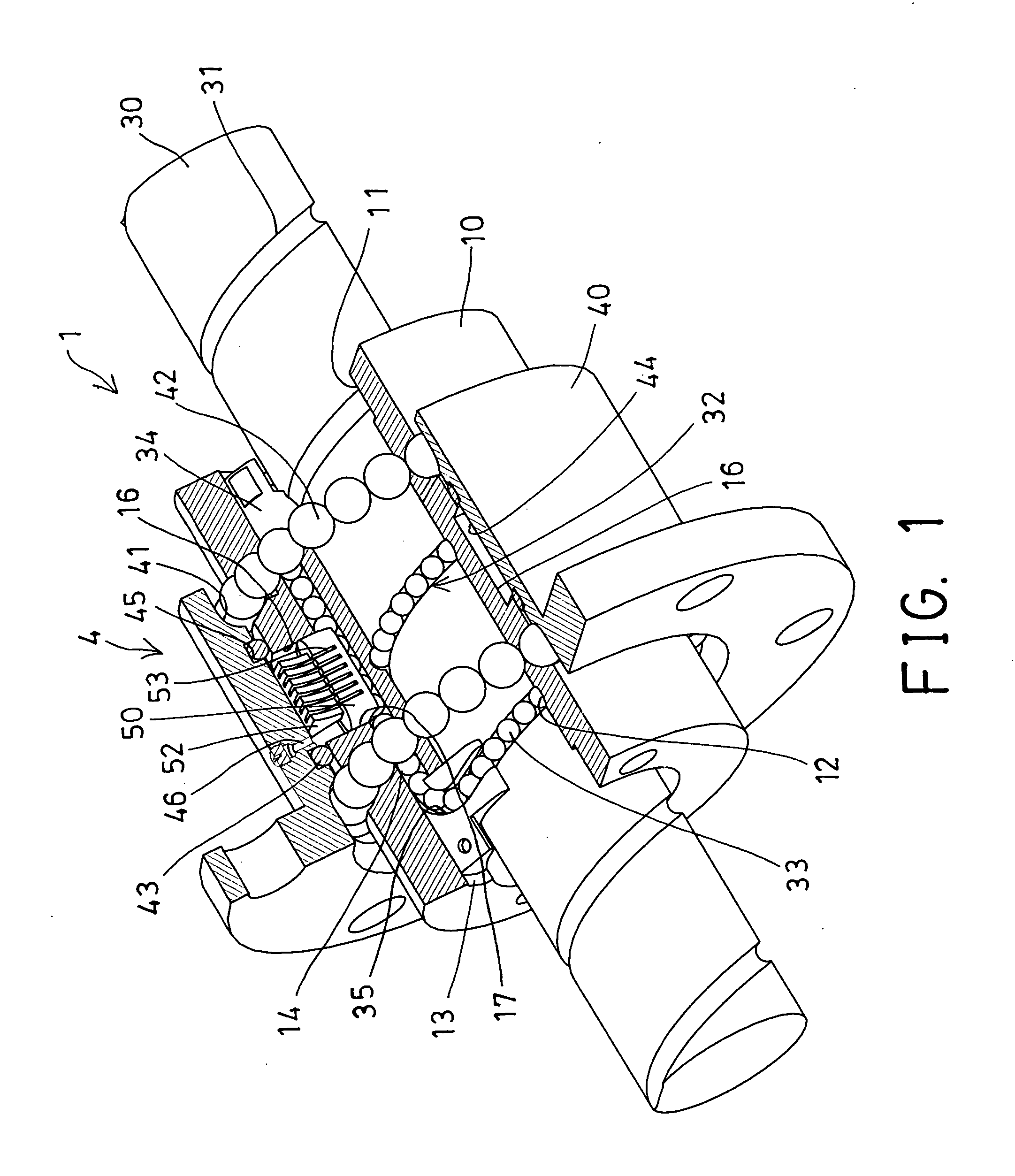
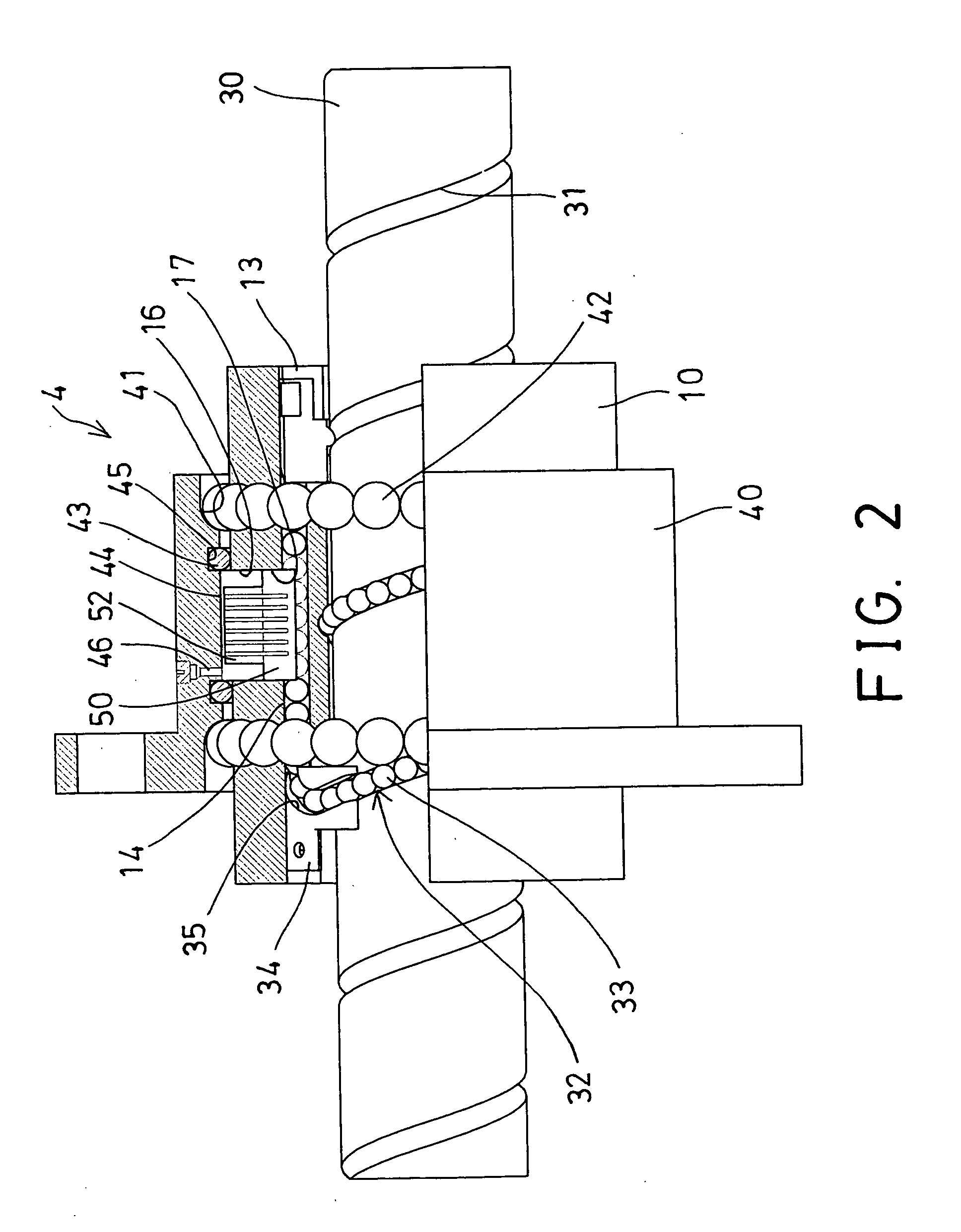
[0024]Referring to the drawings, and initially to FIGS. 1-3, a ball screw device 1 in accordance with the present invention comprises an outer ball nut 10 including a bore 11 formed therein for receiving a typical screw shaft 30 which includes an outer thread 31 formed on the outer peripheral portion thereof, and including an inner thread 12 formed in the ball nut 10 for threading with or for engaging with the outer thread 31 of the screw shaft 30 and thus for allowing the ball nut 10 to be smoothly moved along the screw shaft 30, or for allowing the screw shaft 30 to be smoothly rotated and moved relative to the ball nut 10. The threading engagement and / or the rotational engagement between the ball nut 10 and the screw shaft is typical and will not be described in further details.

[0025]A multiple turn, helical raceway 32 will be formed between the ball nut 10 and the screw shaft 30 by the outer thread 31 of the screw shaft 30 and the inner thread 12 of the ball nut 10 for rotatably...


PUM


Abstract

A ball screw device includes a ball nut having an inner thread and a channel communicating with each other, a screw shaft threaded with the ball nut, a number of bearing members engaged in between the ball nut and the screw shaft and in the channel of the ball nut. A bearing housing is engaged onto the ball nut for forming a sealed annular gap between the bearing housing and the ball nut and for receiving a lubricating oil, and an oil forcing member includes an extension extended into the annular gap that is formed between the bearing housing and the ball nut for forcing or scrubbing or propelling the lubricating oil to flow into the channel in order to lubricate the bearing members.

Description

BACKGROUND OF THE INVENTION[0001]1. Field of the Invention[0002]The present invention relates to a ball screw device, and more particularly to a ball screw device having a lubricating device for effectively and easily lubricating the balls or the bearing members, and for facilitating the rotational movement of the ball nut and the screw shaft relative to each other in great rotational speeds.[0003]2. Description of the Prior Art[0004]Typical ball screw devices comprise a ball nut rotatably and / or moveably engaged onto a screw shaft, and normally arranged to allow the ball nut to be rotated and / or moved relative to the screw shaft in great rotational speeds. For allowing the ball nut to be smoothly rotated and moved relative to the screw shaft, a suitable bearing device or lubricating structure is further required to be provided and engaged between the ball nut and the screw shaft, for facilitating the rotational movement between the ball nut and the screw shaft.[0005]For example, U....

Claims


Application Information

Patent Timeline
Patent Type & Authority Applications(United States)
IPC IPC(8): F16H57/04F16H25/22
CPCF16H25/2214Y10T74/18744F16H57/0497
Inventor CHEN, YAN YUWU, WEN CHIA
Owner HIWIN TECH
Why Eureka
Try Eureka