Bicycle pedal

a pedal body and bicycle technology, applied in the field of bicycle parts, can solve the problems of complex strength and weight reduction of die-castings, requiring expensive tooling, and extensive secondary machining work, so as to facilitate rotational movement of the pedal body, and minimize radial and axial movement.

Active Publication Date: 2011-11-22
BEARCORP
View PDF51 Cites 7 Cited by
  • Summary
  • Abstract
  • Description
  • Claims
  • Application Information

AI Technical Summary

Benefits of technology

[0005]This patent is directed towards a bicycle pedal that separates the function of radial and axial location bearings to enhance strength, performance, and durability. The construction is simplified and allows for the use of composite materials with steel gripping pins. The gripping pins can be easily replaced and since they are supported through the full thickness of the body, they are less likely to cause damage to the pedal body when impacted. The improved construction eliminates the need for an assembly access port at the outboard end of the pedal body.
[0008]A pedal axle comprising an outboard end and an inboard end can be tapered and can have a flanged head at the outboard end. The tapered pedal axle with a flanged head minimizes any type of radial or axial movement. In addition, two types of bearings can be utilized, roller bearings, such as needle bearings; and thrust bearings, such as bushings or cartridge ball bearings, to further minimize radial and axial movement and facilitate rotational movement of the pedal bodies about the pedal axle.

Problems solved by technology

Due to bearing placement requirements, the strength and weight reduction of these die-castings tends to be complex and in many cases they require expensive tooling.
Additionally, they may also require extensive secondary machining work.
Some pedals have been made using plastic bodies, but these also tend to require a complex mold since they generally rely on traditional body design shapes.
Plastic pedals are also usually considered to be too slippery.
This is generally due to the pedal's molded-plastic shoe pins that tend to provide an inferior grip when compared to the steel pins found in metal pedals.
The steel pins in metal pedals, however, normally utilize fixing points that tend to be vulnerable to damage.
This damage usually prevents the fitting of a replacement pin that could be used to prolong the life of the pedal.
In the case of loose ball bearings, the performance is inconsistent, and they rely on regular maintenance and adjustment in order to function properly.
Furthermore, in order to minimize the thickness of the body, which is a desirable feature, the diameter of the spindle is restricted by the ball bearing size, and this in turn compromises strength.
With “sealed” bearing designs, the standard deep groove bearings are either too large or too weak to handle the loads imposed on the pedal design.
Additionally, the use of a bushing-type bearing in this area provides for a less than ideal performance, and axial loads (such as those from dropping the bicycle sideways) can easily destroy the single deep groove cartridge bearing.
This access area is usually capped, but the cover employed is often vulnerable to damage, either making it hard to remove or causing it to either break or fall out, allowing dirt into the bearing cavity.

Method used


Image

  • Bicycle pedal
  • Bicycle pedal
  • Bicycle pedal

Examples


Embodiment Construction

[0018]The detailed description set forth below in connection with the appended drawings is intended as a description of illustrated exemplary embodiments and is not intended to represent the only forms in which these embodiments may be constructed and / or utilized. The description sets forth the functions and sequence of steps for constructing and operating the present invention in connection with the illustrated embodiments. However, it is to be understood that the same or equivalent functions and / or sequences may be accomplished by different embodiments that are also intended to be encompassed within the spirit and scope of the present invention.

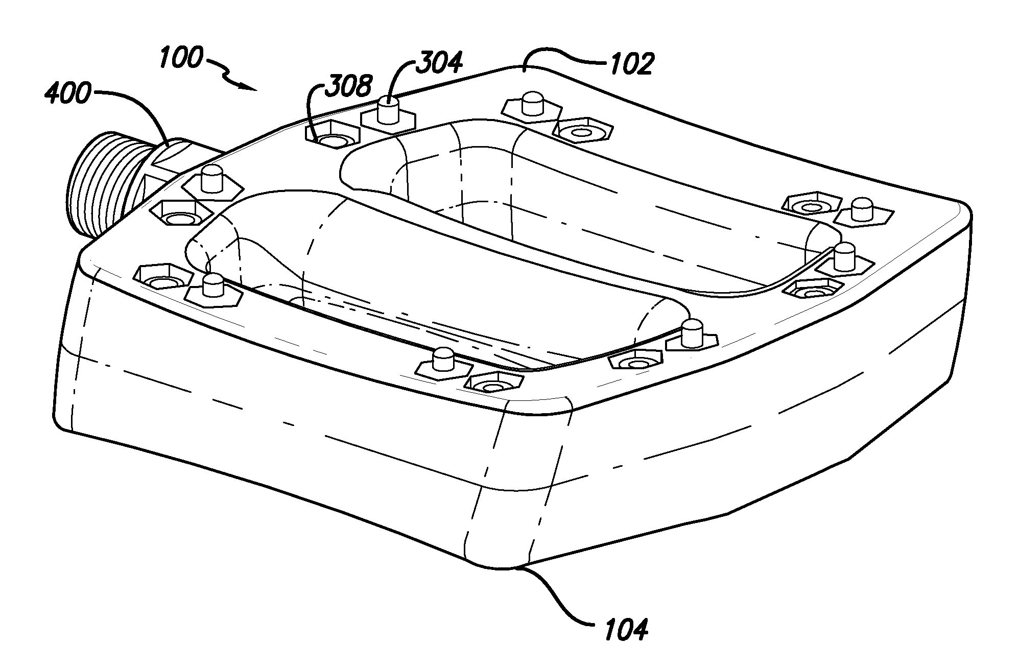
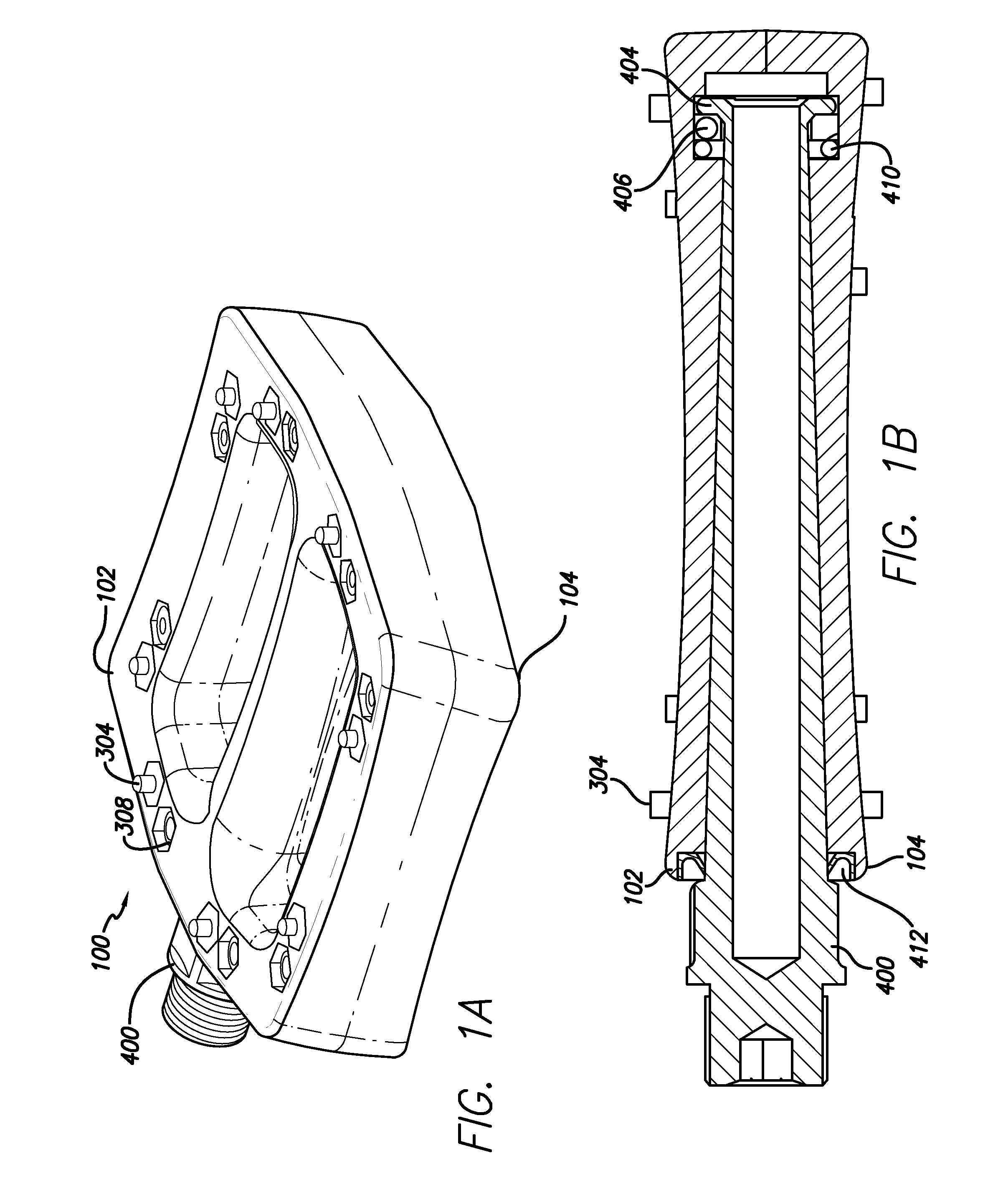
[0019]The present invention is an improved bicycle pedal 100 formed by mating two pedal bodies 102, 104 that are fastened together about a pedal axle 400 with nuts 300 and bolts 302 such that the tail 304 of the bolts 302 that fasten the pedal bodies 102, 104 together serve as traction pins by protruding out and above the outer surface 200 ...


PUM


Abstract

A bicycle pedal apparatus is provided formed from two identical halves comprising a plurality of holes. A bolt secures the two halves through the holes and projects out beyond the surface of the pedal, thereby performing a dual role of securing the two halves together and serving as a traction mechanism. The pedal bodies rotate about a pedal axle either directly on the axle or on bearings. In embodiments utilizing bearings, two different bearings are used, roller bearings to bear the rotational load and thrust bearings to bear any axial load. The pedal axle can be tapered with a flanged head and resides in a cavity in the pedal body that substantially conforms to the shape of the pedal axle so as to minimize movement of the pedal axle within the pedal body.

Description

TECHNICAL FIELD[0001]This invention relates to bicycle parts, particularly, bicycle pedals.BACKGROUND ART[0002]Current bicycle pedal designs are generally comprised of a die-cast body that is formed in one-piece from aluminum or magnesium alloys. Due to bearing placement requirements, the strength and weight reduction of these die-castings tends to be complex and in many cases they require expensive tooling. Additionally, they may also require extensive secondary machining work. Some pedals have been made using plastic bodies, but these also tend to require a complex mold since they generally rely on traditional body design shapes. Plastic pedals are also usually considered to be too slippery. This is generally due to the pedal's molded-plastic shoe pins that tend to provide an inferior grip when compared to the steel pins found in metal pedals. The steel pins in metal pedals, however, normally utilize fixing points that tend to be vulnerable to damage. This damage usually prevents ...

Claims


Application Information

Patent Timeline
Patent Type & Authority Patents(United States)
IPC IPC(8): B62M3/00
CPCB62M3/08Y10T74/2168
Inventor FRENCH, GEORGE
Owner BEARCORP
Why Eureka
Try Eureka