Wave energy conversion device

a technology of wave energy and conversion device, which is applied in the direction of floating buildings, mechanical equipment, machines/engines, etc., can solve the problems of high cost of current technologies, large infrastructure requirements and achieve constant rate upon demand, high compression ratio of piston pumps, and low equipment costs

Inactive Publication Date: 2016-04-12
HON RAPHAEL
View PDF25 Cites 8 Cited by
  • Summary
  • Abstract
  • Description
  • Claims
  • Application Information

AI Technical Summary

Benefits of technology

[0010]Several embodiments of a device to economically harvest wave energy are disclosed. A sealed vessel for air storage, the spar buoy, is mostly submerged under water is also used as an inertial body that surface floats move relative to. The spar buoy may take many geometrical forms, but all have a stem that is above the water surface. Piston pumps are placed at the top of the stem. The pump has a gearing reduction to optimize the rotational motion of the pump drive shaft. Small angular motion at the drive shaft results in multiple cycles of linear reciprocal motion of the piston. Various mechanisms could convert the relative motion between the floats and the spar buoy to a rotational motion of the shaft. The compressed air generated by the pump is stored in the spar buoy and regenerated as electrical energy by expanding the compressed air in a turbine.
[0012]The spar buoy method eliminates the need to build expensive permanent structures at sea. The simple mechanisms in these embodiments keep the equipment costs low. Direct air compression with the piston pump eliminates the need for additional components such as ratchets, clutches, or active control systems to maintain a high compression ratio of the piston pump. Additional components and electronics are not a necessity to generate energy. The irregular wave energy harvested in the form of compressed air can be stored and consumed at a constant rate upon demand. Energy can be harvested from small waves, and the amount of energy harvested is proportional to the wave height. Energy is harvested independent of direction of rotation of the pump crankshaft, i.e. on both the up or down motion of the float. Electrical energy generation may be performed at sea or on shore by transmitting the compressed air to shore through pipelines similarly used for natural gas transport. Alternatively each spar buoy have an electrical generator for producing electricity from the compressed air. Also, a central station comprising at least one electrical generator could be used for producing electricity at sea or another location.

Problems solved by technology

Although wave energy is a large source of renewable energy, it is an underutilized source because current methods and technologies are not economically competitive.
This is due to the high cost of the current technologies or the extensive infrastructure required.
The large infrastructure cost makes the former type expensive while present known methods of relative motion between two floating bodies have high unit cost.
For large scale energy production, these structures have to be designed to withstand high loads at sea which is very costly.
Devices that directly connect the linear motion of a float to the linear motion of a piston pump will only be cost effective for pumping an incompressible fluid such as water or hydraulic fluid.
Incompressible fluids are incapable of storing energy unless they are pumped to a high elevation and stored in a dam.
However, a piston pump will not generate sufficient pressure with compressible fluids unless the piston travels a significant portion of its stroke.
As ocean waves are unpredictable and irregular, the transmission of wave motion directly to a simple piston will only be efficient in a small range of wave heights.
Shallow waves will not generate sufficient compression, and large waves beyond the stroke length of the cylinder are not harvested.
These structures, as described earlier, would be costly to build and maintain.
As discussed previously, the Fletcher invention only works well for pumping liquid, and pumping sea water have undesirable effects for both marine life and the pump.
Many of these inventions that generate electrical energy at sea are inefficient and have high costs.
Very few inventions are in practice or generate energy on a large scale, and even fewer are capable of storing the generated energy.

Method used


Image

  • Wave energy conversion device
  • Wave energy conversion device
  • Wave energy conversion device

Examples


first embodiment

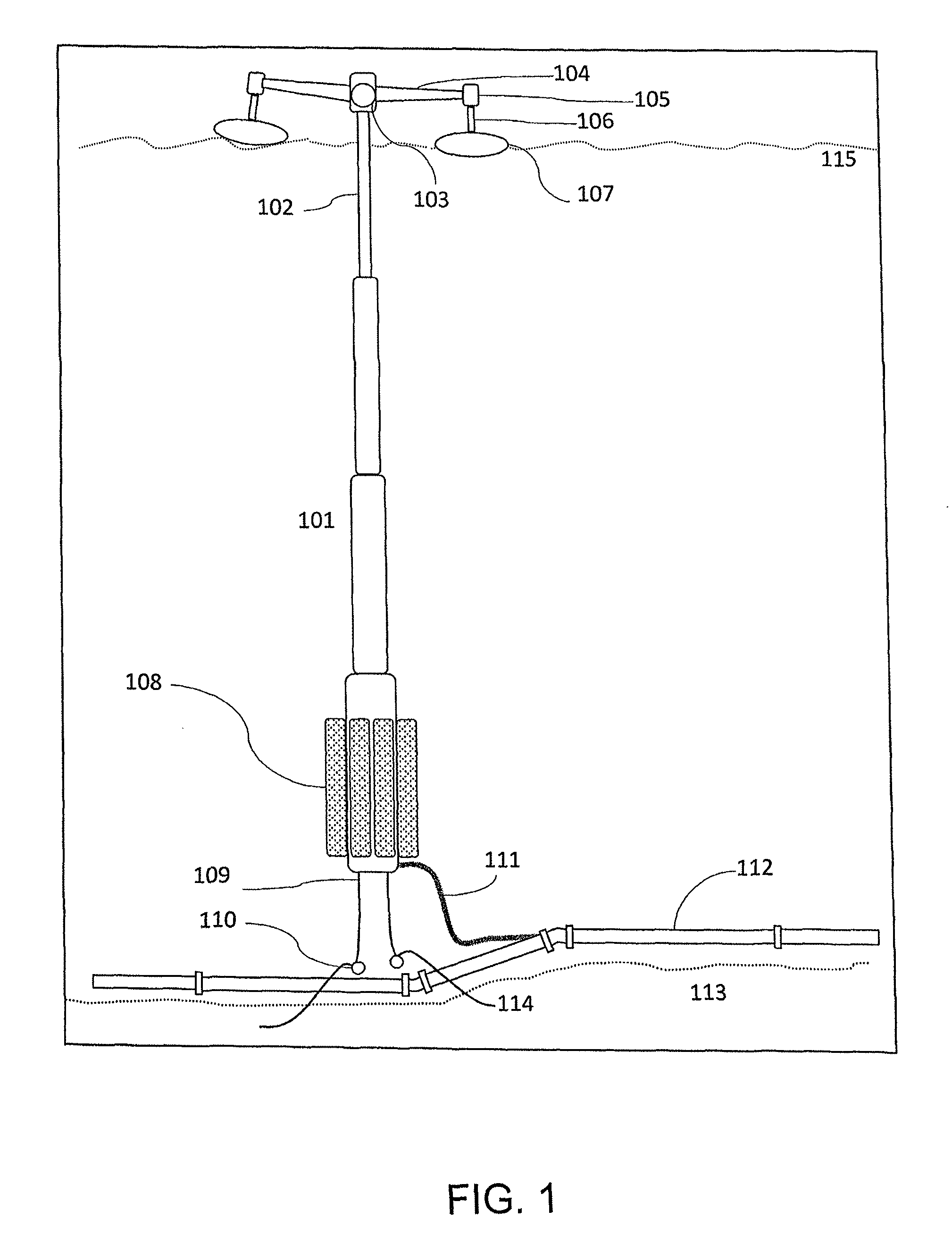
[0025]The main components of a first embodiment are shown in FIG. 1. An elongated hollow vessel, the spar buoy 101, is submerged in the sea with only a smaller tubular beam, the stem 102, protruding through the sea surface. At the top of the stem 102 is an air pump unit 103. A lever arm 104 connected to the drive shaft of the pump unit 103 is rigidly attached to another similar pump unit 105. Similar to lever arm 104, vertical lever arm 106 extends from pump unit 105 is rigidly attached a float 107. The spar buoy 101 is secured with optional weights 108. The mooring chain 109 connected to the body 101 at the deep end secures the entire device. A pipeline hose 111 connects the spar buoy 101 to a submarine pipeline 112. The other end of the chain 109 is secured to the sea bed 113 at a suitable anchoring location 114. Wave motion causes the floats to drive the air pumps to generate compressed air. The compressed air, or other fluid, is returned to the spar buoy 101 for storage and tran...

sixth embodiment

[0059]In a sixth embodiment, the vertical orientation of the spar buoy may be horizontal or angled relative to the surface of the sea, and may be combined with the vertical orientation. FIG. 6 shows a horizontal spar buoy 601 which is connected to multiple vertical spar buoys 602 and stems 603. The function of the spar buoy 601 remains the same, providing a large inertial mass as well as storage for the compressed air. The vertical spar buoys 602 of FIG. 6 need not be included, so that the horizontal spar buoy 601 is directly connected to stems 603. Multiple stems 603 may be connected to a single spar buoy 601 in a horizontal orientation, and multiple horizontal spar buoys may be combined to form a network of stems 603 and bodies 601.

[0060]The float and pump unit 604 combination may be any of the embodiments described above. As in the first embodiment, weights 605 may be attached to the bottom of the spar buoy 601 to maintain the buoyant stability. Auxiliary floats may be used to su...


PUM


Abstract

Several embodiments of a device for economically harvesting wave energy are disclosed. A sealed vessel for air storage, the spar buoy, is mostly submerged under water is also used as an inertial body that surface floats move relative to. The spar buoy may take many geometrical forms, but all have a stem that is above the water surface. Piston pumps are placed at the top of the stem. The pump has a gearing reduction to optimize the rotational motion of the pump drive shaft. Small angular motion at the drive shaft results in multiple cycles of linear reciprocal motion of the piston. Various mechanisms could convert the relative motion between the floats and the spar buoy to a rotational motion of the shaft. The compressed air generated by the pump is stored in the spar buoy and regenerated as electrical energy by expanding the compressed air in a turbine.

Description

CROSS-REFERENCE TO RELATED APPLICATIONS[0001]The present application is a U.S. National Phase Application of International Application PCT / US2010 / 055366, filed on Nov. 04, 2010, which claims the benefit of U.S. Provisional Application No. 61 / 258,851, filed on Nov. 06, 2009, all of which are herein incorporated by reference in their entirety.FIELD OF THE INVENTION[0002]This application relates to a wave energy conversion device through air compression.BACKGROUND OF THE INVENTION[0003]Renewable energy is currently a small portion of society's energy generation compared to fossil fuels energy sources. Although wave energy is a large source of renewable energy, it is an underutilized source because current methods and technologies are not economically competitive. This is due to the high cost of the current technologies or the extensive infrastructure required. In addition, the technology should not pose a threat to marine life or cause other environmental damage. Ideally, the harvested...

Claims


Application Information

Patent Timeline
Patent Type & Authority Patents(United States)
IPC IPC(8): F03B13/18F03B13/20F03B13/16F03B13/12F03B13/24B63B35/44
CPCF03B13/1815F03B13/12F03B13/16F03B13/18F03B13/181F03B13/1805F03B13/20F03B13/24B63B2035/4466F05B2210/404F05B2240/40F05B2240/93F05B2240/95F05B2250/411F05B2260/4021F05B2260/4031Y02E10/20Y02E10/32Y02E10/38F03B13/186Y02E10/30
Inventor HON, RAPHAEL
Owner HON RAPHAEL
Why Eureka
Try Eureka