Valve for equalizer sand screens

a technology of equalizer sand and valve, which is applied in the direction of valve operating means/release devices, sealing/packing, and borehole/well accessories, etc., can solve the problem of not being able to ensure that all the rupture discs will break at the same tim

Active Publication Date: 2008-06-12
BAKER HUGHES INC
View PDF15 Cites 41 Cited by
  • Summary
  • Abstract
  • Description
  • Claims
  • Application Information

AI Technical Summary

Problems solved by technology

While a possible solution is to plug the inflow openings with a rupture disc, the problem with that is that there is no assurance all the rupture discs will break at the same time.

Method used


Image

  • Valve for equalizer sand screens
  • Valve for equalizer sand screens
  • Valve for equalizer sand screens

Examples


Embodiment Construction

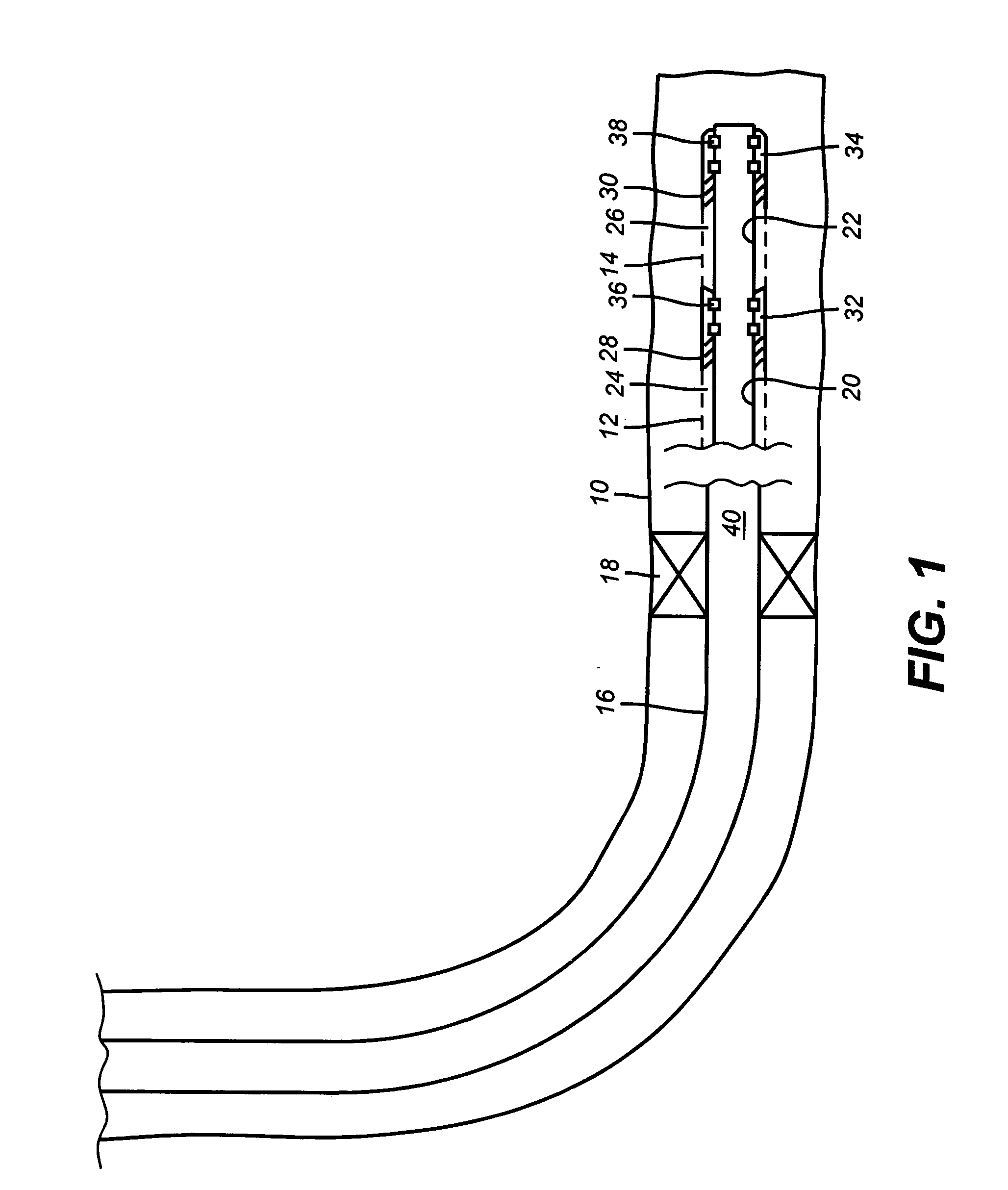
[0026]FIG. 1 illustrates a horizontal interval 10 that is uncased and has a series of Equalizer screens 12 and 14, for example connected to a production string 16. A packer 18 is connected to string 16. Base pipes 20 and 22 are solid. Annular spaces 24 and 26 lead to restrictors 28 and 30 respectively. These restrictors are essentially a spiral path whose dimensions determine resistance to the filtered fluid that has gotten through the screens 12 and 14. After passing through the restrictors 28 and 30, the filtered fluid enters annular spaces 32 or 34 to reach respectively the valves 36 and 38 that are a part of the present invention. When valves 36 and 38 are closed, pressure in passage 40 can be built up so that, for example, the packer 18 can be set. In other applications, the lower end can have a mud motor and drill bit attached so that drilling that brings the screens 12 and 14 into position in horizontal interval 10 can be accomplished and afterward the valves 36 and 38 can be...


PUM


Abstract

A series of screens with restrictors to equalize flow through base pipe perforations downstream or upstream of each restrictor features a valve member in the openings so that the screens are closed to flow for run in. Pressure can be developed within the base pipe for operation of downhole equipment below the screens such as a mud motor or in the screen liner such as a packer with no need for an internal string or wash pipe. The openings can be opened selectively when the associated equipment connected to the base pipes has been operated. The valve member can be actuated to open in a variety of ways such as applied pressure, temperature or a change in well fluid condition.

Description

FIELD OF THE INENTION[0001]The field of this invention relates to isolation valves for screens that allow the screens to be selectively closed to operate other equipment.BACKGROUND OF THE INVENTION[0002]In some long horizontal completions steps are taken to reduce the tendency of produced fluids to run along the outside of screens until reaching a necking down of the annular space outside the screened interval before making an attempt to go through the screen, usually on the uphole or heel end of the screen interval. To counteract this effect, the screen sections are provided with a non-perforated base pipe under the screen section that forces the fluid along an annular path between the base pipe and the screen until a restriction section is reached. The restriction section can be a spiral path that provides a flow restriction to the filtered fluid. After going through the spiral restriction section, the filtered fluid reaches the openings to go though the base pipe. This product is...

Claims


Application Information

Patent Timeline
Patent Type & Authority Applications(United States)
IPC IPC(8): E21B34/08
CPCE21B34/102E21B34/14E21B43/14E21B43/12E21B43/08Y10T137/86485
Inventor CORONADO, MARTIN P.PICKLE, BRAD R.
Owner BAKER HUGHES INC
Why Eureka
Try Eureka