Container and cooker

a technology for containers and cookers, applied in the field of containers and cookers, can solve the problems of container slipping out of the top heating platform very easily, substantial chance, and container misplacement on the top heating platform, and achieve the effect of efficient and effective heat transfer

Inactive Publication Date: 2008-06-12
HUARUN APPLIANCE
View PDF7 Cites 0 Cited by
  • Summary
  • Abstract
  • Description
  • Claims
  • Application Information

AI Technical Summary

Benefits of technology

[0008]A main object of the present invention is to provide to a cooking set which comprises a heating unit and a container, wherein the cooker unit is capable of evenly transmitting heat to the container so as to achieve efficient and effective heat transfer between the cooker unit and the container.

Problems solved by technology

There exist several disadvantages in relation to these conventional cookers.
First, almost all containers rely on a single bottom surface as the main heat transmitting surface.
Thus, when one places the container onto the top heating platform, there is substantial chance that the container is misplaced onto the top heating platform (i.e. not at its central portion).
Moreover, the container would slip out of the top heating platform very easily during the course of cooking.
Second, almost all conventional containers have more or less identical physical structure, which prohibits effective heat transfers when used in conjunction with the above-mentioned conventional heating bases.
Since heat transfer within the container is mainly by convection, it is predictable that it would take very long time for the heating base to heat up the objects, especially water, stored within the container.
In other words, one needs substantial amount of energy to raise the water temperature and this will take very long time when conventional electric cookers are utilized.
Third, since heat transfer from the heating base to the container is by a combination of conduction and convection, there would certainly be substantially uneven distribution of heat within the container.

Method used


Image

  • Container and cooker
  • Container and cooker
  • Container and cooker

Examples


Embodiment Construction

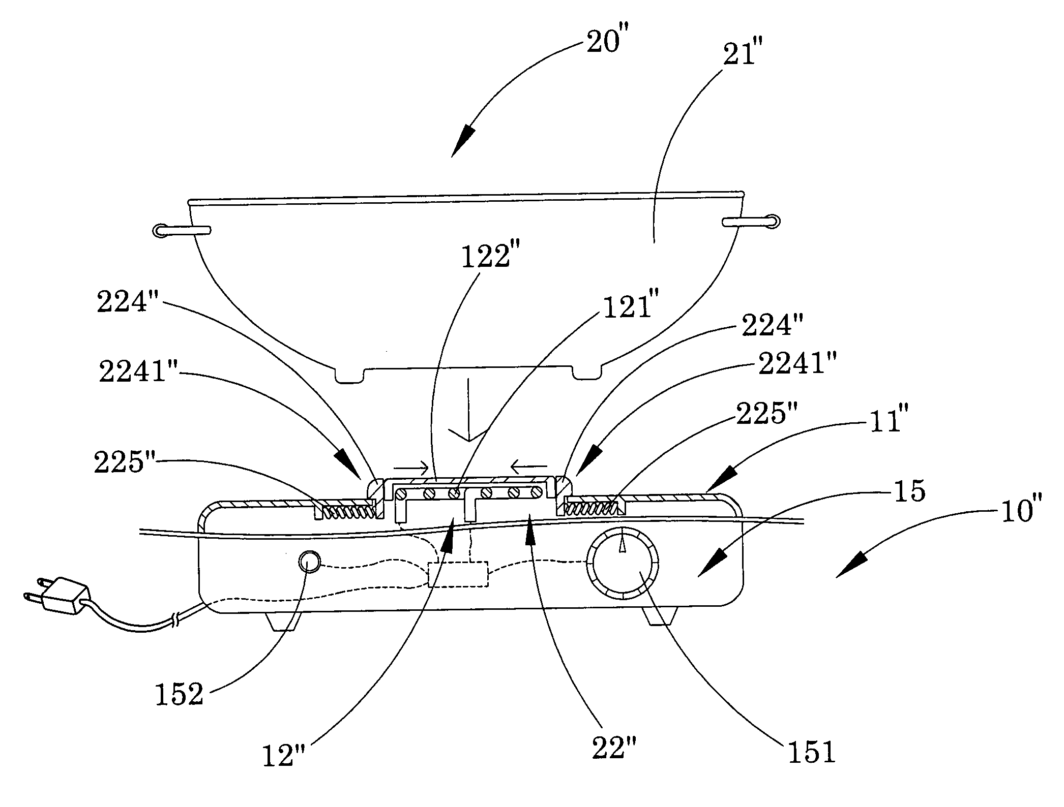
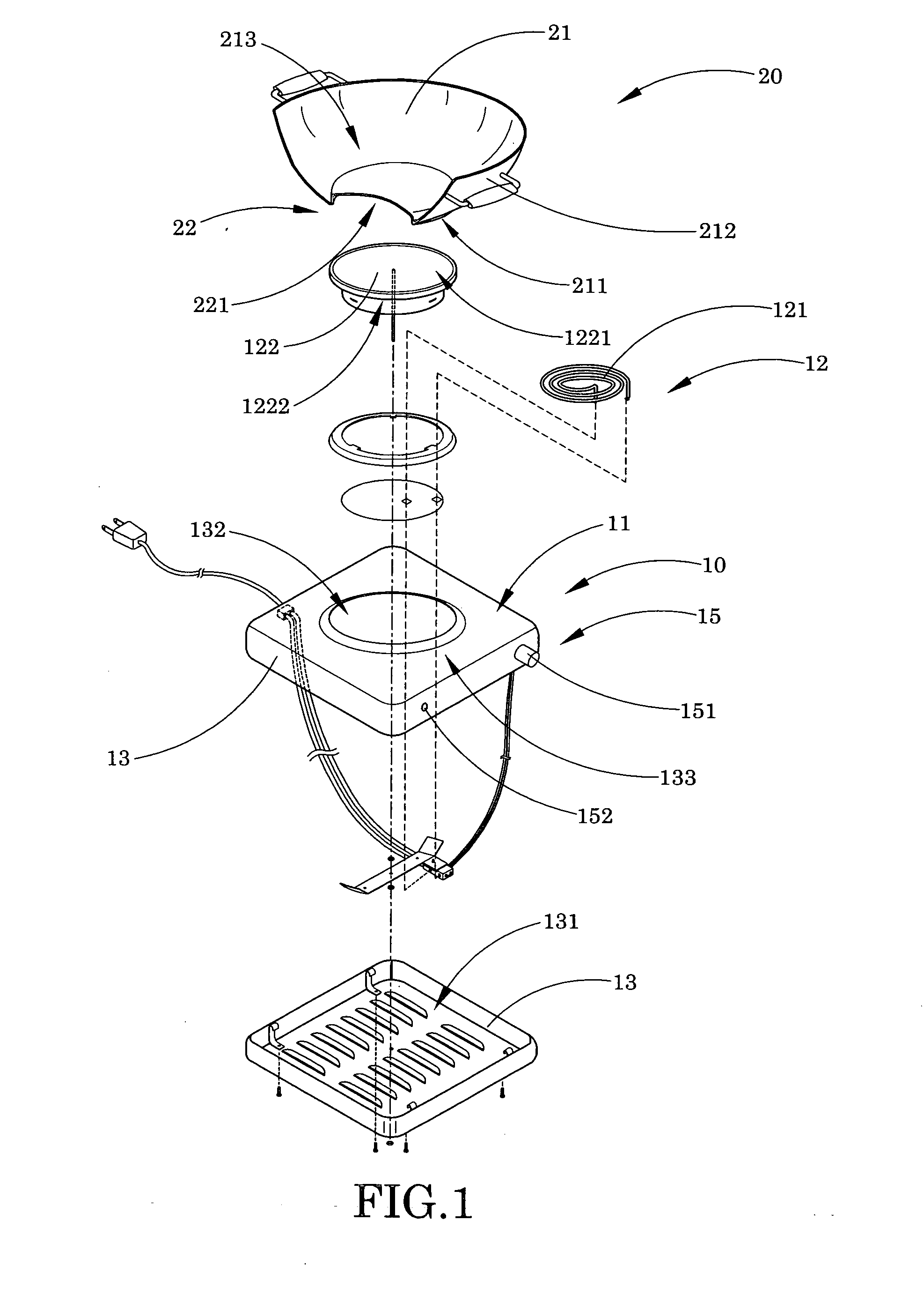
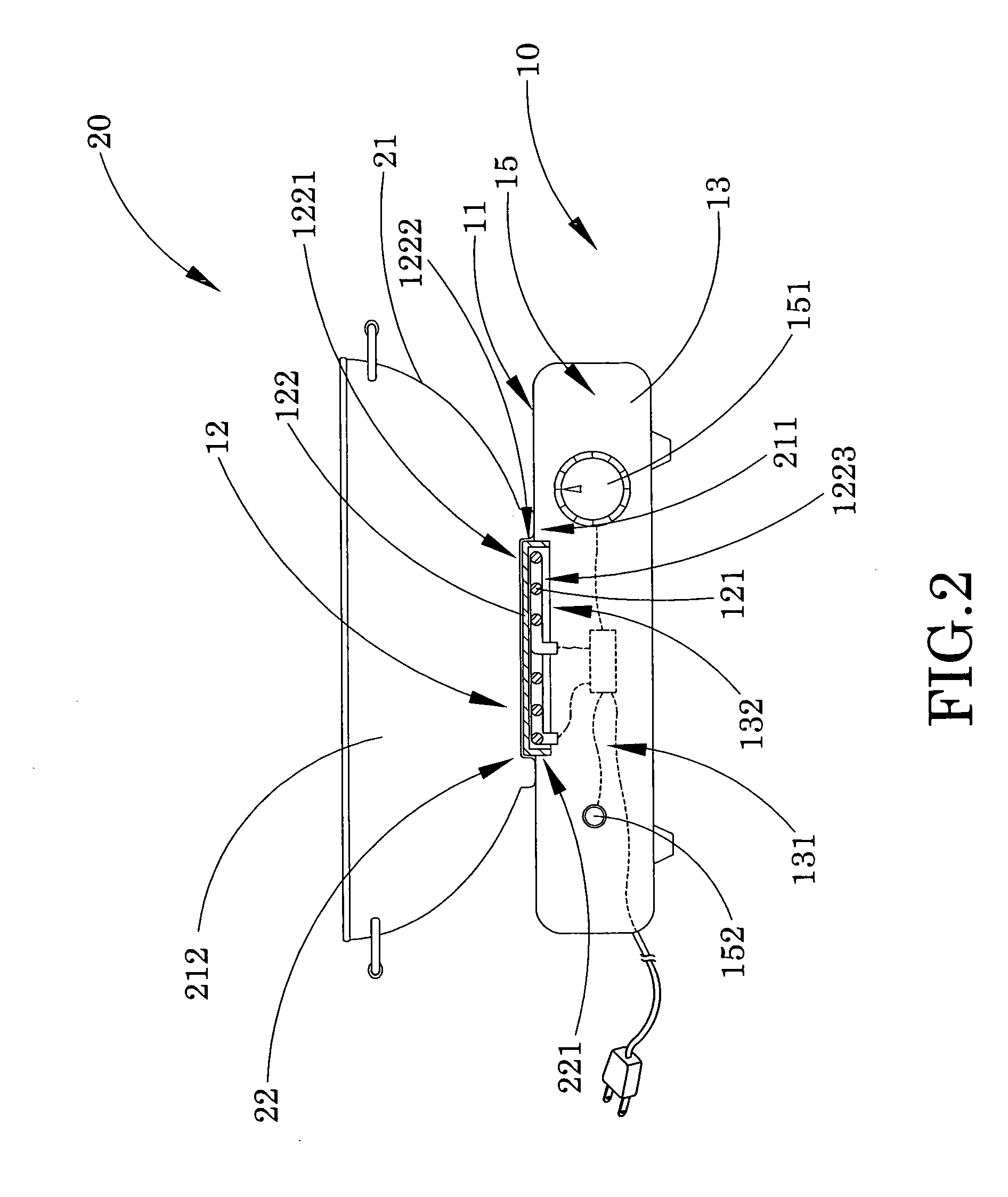
[0022]Referring to FIG. 1 to FIG. 2 of the drawings, a cooking set according to a preferred embodiment of the present invention is illustrated, in which the cooking set comprises a heating unit 10 and a container 20. The heating unit 10 has a top platform 11 and a heat source 12 provided thereon for generating heat.

[0023]The container 20 comprises a container body 21 and a heat enhancement arrangement 22. The container body 21 comprises a bottom wall 211 and a surrounding wall 212 upwardly extended from the bottom wall 211 to form a heating cavity 213 within the bottom wall 211 and the surrounding wall 212.

[0024]The heat enhancement arrangement 22 contains a heat distributing cavity 221 indently formed on the bottom wall 211 of the container 20 to align with the heat source 12 when the container body 21 is sat on the top platform 11 of the heating unit 10, and comprises a heat transfer member 122 which is provided on the top platform 11 and is aligned with the heat distributing cavi...


PUM


Abstract

A cooking set includes a heating unit, and a container. The heating unit has a top platform and a heat source provided thereon for generating heat. The container includes a container body and a heat enhancement arrangement. The container body includes a bottom wall and a surrounding wall upwardly extended from the bottom wall to form a heating cavity within the bottom wall and the surrounding wall. The heat enhancement arrangement contains a heat distributing cavity indently formed on the bottom wall of the container body to align with the heat source of the heating unit when the container body is disposed on the top platform of the heating unit, such that when the heating unit is controllably operated to generate the heat via the heat source, the heat is evenly accumulated within the heat distributing cavity to evenly distribute from the bottom wall to the surrounding wall.

Description

BACKGROUND OF THE PRESENT INVENTION[0001]1. Field of Invention[0002]The present invention relates to a cooking set, and more particularly to a cooker unit which is capable of evenly transmitting heat to a container so as to achieve efficient heat transfer between the cooker unit and the container.[0003]2. Description of Related Arts[0004]A conventional electric cooker usually comprises a heating base having a top heating platform formed thereon, and a heating module received within the heating base and thermally communicated with said top heating platform in such a manner that when a container is placed on top of the top heating platform, the heating module is arranged to transfer energy to the top heating platform which in turn transfers such energy to the container so as to heat up the object contained within the container. For example, if the container contains a predetermined amount of water, when the heating module is activated, energy is transferred to the top heating platform...

Claims


Application Information

Patent Timeline
Patent Type & Authority Applications(United States)
IPC IPC(8): H05B3/02H05B3/68H05B3/10
CPCH05B3/68A47J36/34
Inventor WU, CINDYWU, LEE K.
Owner HUARUN APPLIANCE
Why Eureka
Try Eureka