Low-cost solar energy tracking and condensing power generation method

A technology of solar tracking and solar energy, applied in the field of solar utilization, can solve the problems of high cost, high cost, and high cost, and achieve the effects of strong cycle power, reduced structural cost, and low wind resistance

Inactive Publication Date: 2009-09-02
张玉良
View PDF2 Cites 36 Cited by
  • Summary
  • Abstract
  • Description
  • Claims
  • Application Information

AI Technical Summary

Problems solved by technology

[0002] At present, the development of solar power generation and heat utilization technology is relatively fast. In the field of solar heat utilization, solar low-temperature water heaters develop rapidly, but in the field of medium and high temperature, there are few applications due to high technical costs.
Solar power generation mainly includes solar photovoltaic power generation (solar cells) and solar thermal power generation, but the common problem is still the high cost of power generation
The raw material cost of the former crystalline silicon is difficult to break through. Whether the latter is concentrating with a dish reflector, a trough reflector or a tower planar reflector, the general idea is to increase the size of a single heat collector, and each reflector Using an independent tracking control system, the result is that the complex and bulky heat collection system is always difficult to reduce the cost of power generation for solar energy with a very low energy flux density
[0003] At present, the thermal units used in solar thermal power generation have low thermal efficiency due to the inability to achieve large capa

Method used


Image

  • Low-cost solar energy tracking and condensing power generation method
  • Low-cost solar energy tracking and condensing power generation method
  • Low-cost solar energy tracking and condensing power generation method

Examples


Example Embodiment

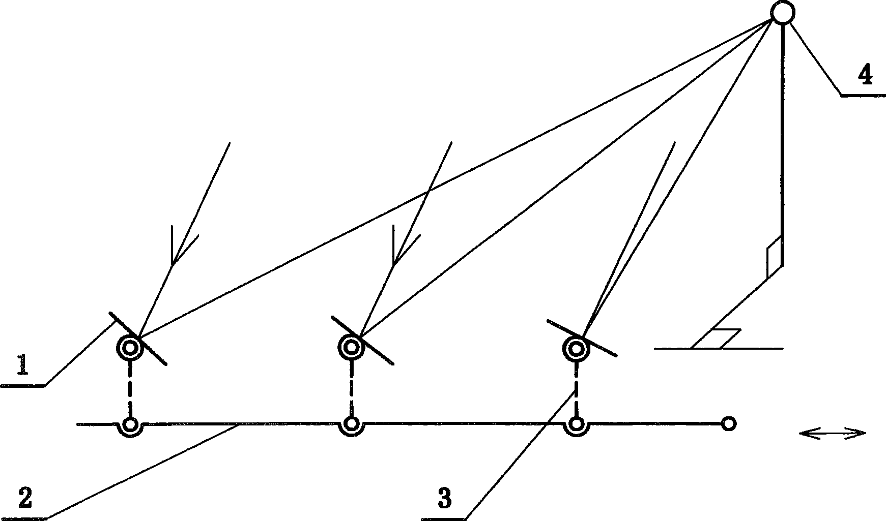
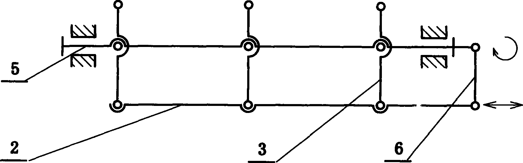
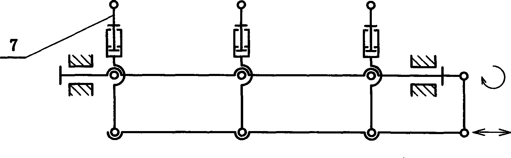
[0065] Embodiment 1: In order to realize low-cost solar reflectors tracking and concentrating, adopt as attached figure 1 In the connecting rod linkage mode shown, in order to realize reflection and light concentrating, each reflector 1 is installed at an appropriate installation angle, and under the action of the movement of the connecting rod 2, the parallel rocker 3 parallel to each other realizes synchronous deflection. The deflection of the sun's rays makes the reflected light change synchronously and focus on the receiver 4, forming a parallel link tracking and concentrating system. Generally, the two-dimensional deflection of the entire array is controlled by connecting rods in the vertical and horizontal directions. figure 1 Only one row of mirrors is shown in the figure, and when arranged in multiple rows, it becomes a mirror concentrating array. When the parallel linkage mechanism of each row is horizontal, the longitudinal deflection of the mirror is realized by the...

Example Embodiment

[0075]Embodiment 2: as attached Figure 13 The shown simple power heat pipe circulation system is filled with a part of the working medium (which can be water or other suitable solutions), and vacuumizes to remove the air seal so that the working medium can evaporate at a lower temperature. When the heater 22 is heated When the working medium starts to evaporate and expand to generate pressure, the check valve 21 is reversely closed, and the working medium starts to flow to the condenser 24, and after passing through the condenser, it is condensed into a liquid state and enters the return pipe 25. When the working medium in the heater evaporates, its internal The pressure gradually drops, and finally the pressure of the gas working medium before and after the condenser is close to the same, and the whole circuit becomes a connector, and the liquid working medium in the return pipe pushes the check valve to lead forward and enter the heater to start a new cycle. The graphics of...

Example Embodiment

[0086] Embodiment 3: as attached Figure 18 As shown, a thermodynamic booster power heat pipe cycle power generation system can be considered as a cycle system in which a thermodynamic booster system is used to replace the feed water pump on the basis of an ordinary thermal power generation system. The working process of the thermodynamic booster is:

[0087] a. Hydration. When the thermal booster 41 needs to replenish water, open the steam vent valve 43 of the condensed water tank 44 and close other valves, and the low-pressure liquid working medium from the condensed water tank 44 enters the booster 41 through the check valve 42 due to the principle of the connector.

[0088] b. Boost. After the booster replenishment is completed, the steam vent valve 43 is closed, and the steam extraction valve 46 is opened. Close the steam extraction valve 46 during the time, open the steam vent valve 37 with the evaporator 39 to continue heating and boosting.

[0089] c. Water supply. ...


PUM


Abstract

The invention provides a low-cost solar energy tracking and condensing power generation method, belongs to the field of solar utilization, relates to solar energy condensing light and heat power generation and condensing photovoltaic power generation and solar energy condensing light and heat utilization, and realizes a whole low-cost proposal for solar energy power generation through technical breakthroughs in various links. The method comprises that: a parallel linkage and a compensation mechanism control a reflecting mirror array to trace and condense light in low cost; heat induction of a power thermotube of an inverted valve is added to a thermotube cycle for evaporation and condensation; container type heat evaporation and pressurization replaces a feed pump to make a heat power generation cycle freely select working media for high-efficiency fully-enclosed operation; and a simple linear motor type hydrothermomagnetic power generation method can make the heat pressurization power generation cycle have higher efficiency and lower cost, make thermotubes on solar cell backboards radiate heat, condense light, generate power and the like. The low-cost whole resolution proposal can promote wide use of solar energy, and the technical breakthroughs in the various links can play important roles in saving energy in respective fields.

Description

technical field [0001] The invention belongs to the field of solar utilization, and relates to an efficient heat dissipation method for concentrated solar thermal power generation, solar concentrated thermal utilization, and photovoltaic cell concentrated power generation. Background technique [0002] At present, the development of solar power generation and heat utilization technology is relatively fast. In the field of solar heat utilization, solar low-temperature water heaters develop rapidly, but in the field of medium and high temperature, there are few applications due to high technical costs. Solar power generation mainly includes solar photovoltaic power generation (solar cells) and solar thermal power generation, but the common problem is still the high cost of power generation. The raw material cost of the former crystalline silicon is difficult to break through. Whether the latter is concentrating with a dish reflector, a trough reflector or a tower planar reflec...

Claims


Application Information

Patent Timeline
IPC IPC(8): H02N6/00F24J2/38F24J2/54F24J2/04H02N11/00H02K44/08H02S20/32
CPCY02E10/50
Inventor 张玉良
Owner 张玉良
Why Eureka
Try Eureka