Plasma display panel and plasma display device having the same

a plasma display panel and display panel technology, applied in the direction of incadescent cooling arrangement, discharge tube main electrode, electrical apparatus construction details, etc., can solve the problems of large heat generation of plasma display panel, different temperature gradients on the surface of the panel, and the inability to quickly transfer heat generated by the plasma display panel to the chassis base, etc., to achieve the effect of improving the structure and enhancing the heat transfer efficiency of the plasma display panel

Inactive Publication Date: 2005-04-14
SAMSUNG SDI CO LTD
View PDF2 Cites 45 Cited by
  • Summary
  • Abstract
  • Description
  • Claims
  • Application Information

AI Technical Summary

Benefits of technology

[0011] The present invention provides a plasma display device having an improved structure that can enhance heat transfer efficiency of a plasma display panel.
[0012] The present invention also provides a plasma display device that may achieve an efficient heat transfer without mounting an additional heat dissipation means between the plasma display panel and a chassis base.
[0013] The present invention also provides a plasma display device that may prevent heat-induced generation of latent images or reduced brightness by rapidly removing uneven temperature gradients on a plane of the plasma display panel.
[0014] The present invention also provides a plasma display device that may efficiently dissipate heat generated by other electrical devices on the plasma display panel without using an additional heat dissipator.
[0015] The present invention further provides a plasma display device having an improved heat dissipation structure that may make the plasma display device easy to modify or maintain.
[0020] The heat radiation coating layer may be formed on a surface of the plasma display panel facing the chassis base. At this time, the heat radiation coating layer may be formed with a low brightness color for improving contrast.

Problems solved by technology

In a plasma display device, the discharge used to display images on the plasma display panel generates a large amount of heat.
The heat generated is not distributed on a surface of the panel uniformly but is distributed unevenly according to operating conditions such as strength of discharge, thereby creating different temperature gradients on the surface of the panel.
However, since the heat dissipation sheet generally has a low thermal conductivity such as a thermal conductivity coefficient of approximately 1 W / mK, heat generated by the plasma display panel may not be rapidly transferred to the chassis base.
Consequently, heat transfer efficiency is reduced.
Also, since conventional heat dissipation sheets have low thermal conductivity, the heat radiation in a plane direction is not fluent, and this results in a sectional temperature increase on the panel.
As a result, a bright latent image, that is, a brightness difference between cells, may occur, thereby reducing the panel's overall brightness.
However, the high thermal conductivity heat dissipation sheet is hard to attach to and detach from the panel.

Method used


Image

  • Plasma display panel and plasma display device having the same
  • Plasma display panel and plasma display device having the same
  • Plasma display panel and plasma display device having the same

Examples


Embodiment Construction

[0034] Hereinafter, the present invention will be described more fully with reference to the accompanying drawings in which embodiments of the invention are shown.

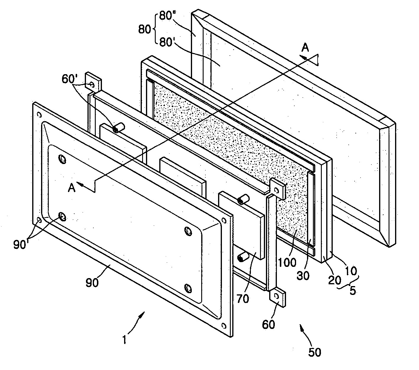
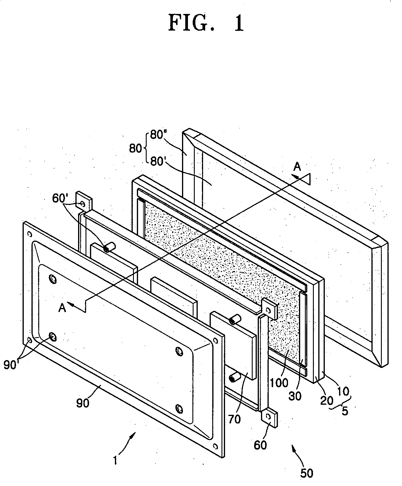
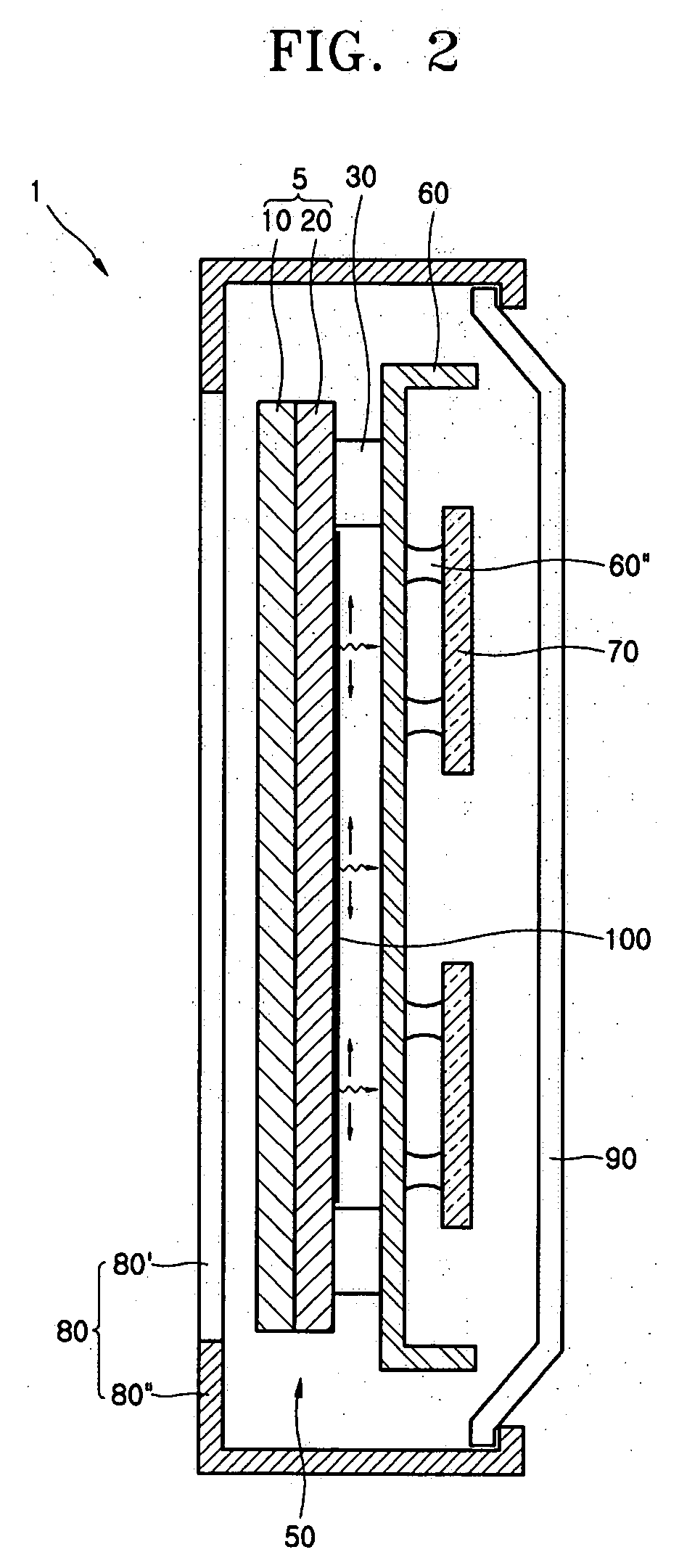
[0035]FIG. 1 is an exploded perspective view of a plasma display device according to an embodiment of the present invention. FIG. 2 is a cross- sectional view taken along line A-A in FIG. 1. FIGS. 3 through 6 are cross- sectional views of plasma display devices according to different embodiments of the present invention.

[0036] Referring to FIGS. 1 and 2, a plasma display device 1 includes a plasma display module 50, a front cover 80 and a back cover 90 that house the plasma display module 50.

[0037] The plasma display module 50 includes a plasma display panel 5, a chassis base 60, and a circuit unit 70 disposed on a back side of the chassis base 60.

[0038] The plasma display panel 5 includes a front panel 10 and a rear panel 20 in a combined state. The plasma display panel 5, which may be formed of glass, becomes an imag...


PUM


Abstract

A plasma display panel having improved heat transfer efficiency and temperature distribution, and a plasma display device including the same are disclosed. The plasma display device includes a plasma display module that includes a plasma display panel on which an image is displayed, a chassis base facing the plasma display panel, a circuit unit disposed at a back side of the chassis base for driving the plasma display panel, a front cover and a back cover that house the plasma display module, and at least a heat radiation coating layer formed between the front cover and the back cover. The heat radiation layer reduces a conventional heat dissipation sheet unnecessary, and thus reduces process times and manufacturing costs.

Description

BACKGROUND OF THE INVENTION [0001] This application claims priority to Korean Patent Application No. 2003-70269, filed on Oct. 9, 2003, in the Korean Intellectual Property Office, the disclosure of which is herein incorporated by reference in its entirety. [0002] 1. Field of the Invention [0003] The present invention relates to a plasma display device, and more particularly, to a plasma display device with a structure that facilitates heat radiation from a circuit device. [0004] 2. Description of the Related Art [0005] A plasma display device (PDD) is a flat panel display device for displaying pictures by using a discharge effect. Because of its very good performance and characteristics such as high display capacity, high brightness, high contrast, clear latent image, and large viewing angle, and it is thin with a large screen size, the PDD may replace cathode ray tube (CRT) display devices. [0006] In a plasma display device, the discharge used to display images on the plasma displa...

Claims


Application Information

Patent Timeline
Patent Type & Authority Applications(United States)
IPC IPC(8): H01J17/28H01J17/49H05K7/20
CPCH01J2217/492H05K7/20972H05K7/20963H01J17/28
Inventor KIM, SOK-SANCHO, IN-SOO
Owner SAMSUNG SDI CO LTD
Why Eureka
Try Eureka