Stator for an electric motor having a temperature monitor

a technology of temperature monitor and electric motor, which is applied in the direction of dynamo-electric machines, data recording, structural associations, etc., can solve the problems of unoptimized thermal transfer, achieve high reliability in use, reduce manufacturing and assembly costs, and improve heat transfer efficiency

Active Publication Date: 2008-07-22
EBM PAPST MULFINGEN GMBH & CO KG
View PDF24 Cites 45 Cited by
  • Summary
  • Abstract
  • Description
  • Claims
  • Application Information

AI Technical Summary

Benefits of technology

[0006]According to the invention, the temperature monitor is thus held in an integrated manner in an insulating switching disk, which covers, in particular covers in the form of a cap, the region of the end winding such that, on the end-winding side, it rests between the stator winding and the switching disk such that it is in thermally conductive bearing contact with the stator winding. This means that the temperature monitor—preferably together with further contact elements of the connecting arrangement—is held in an integrated manner in the switching disk in preassembled form such that only the switching disk which has been provided in advance in this manner needs to be placed axially onto the wound laminated stator core. In this case, the temperature monitor bears, in direct bearing contact, against the stator winding on the end-winding side, which ensures effective heat transfer and, as a result, a high degree of reliability owing to the fact that the temperature monitor reliably disconnects the motor in the event of overheating.
[0007]In one advantageous refinement, the temperature monitor is fixed in the switching disk by means of its connecting wires, for which purpose the switching disk has fixing elements on its stator side facing the end winding for the purpose of accommodating and holding, in a clamping manner, the connecting wires. In addition, a spring-elastic pressure force is preferably applied to the temperature monitor, for which purpose the switching disk has a spring arm, which produces the pressure force, in the region of the temperature monitor. Owing to this advantageous refinement, tolerance compensation is achieved by any dimensional tolerances; in particular tolerances of the installation height of the end winding, being compensated for by the spring-loading of the temperature monitor such that, in any event, effective, direct thermal contact between the temperature monitor and the stator winding is ensured.
[0009]Further advantageous design features will be explained in more detail below.

Problems solved by technology

Thermal transfer is therefore not optimal.

Method used


Image

  • Stator for an electric motor having a temperature monitor
  • Stator for an electric motor having a temperature monitor
  • Stator for an electric motor having a temperature monitor

Examples


Embodiment Construction

[0027]In the various figures of the drawing, identical parts are always provided with the same references and therefore generally only need to be described once in each case.

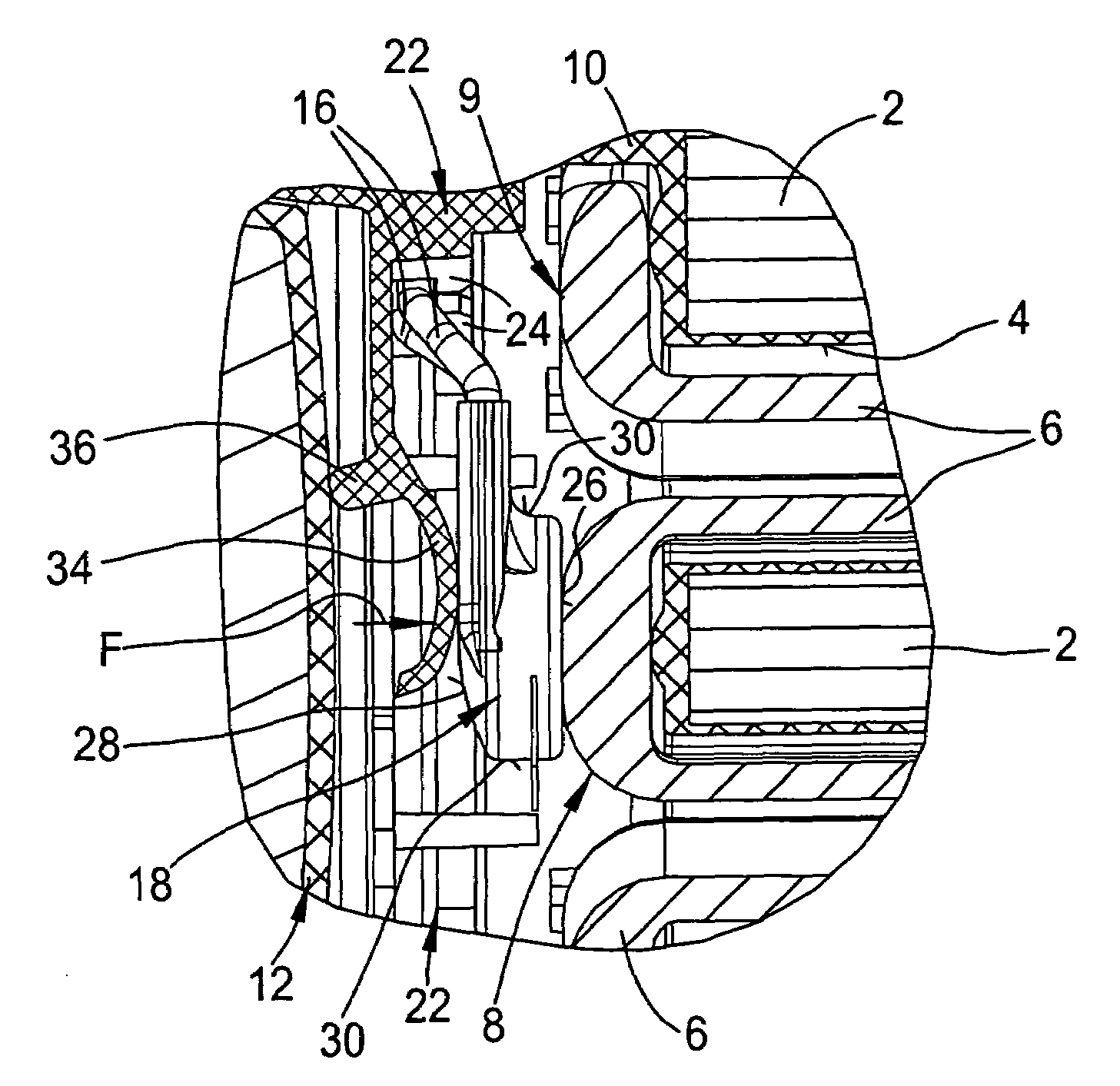
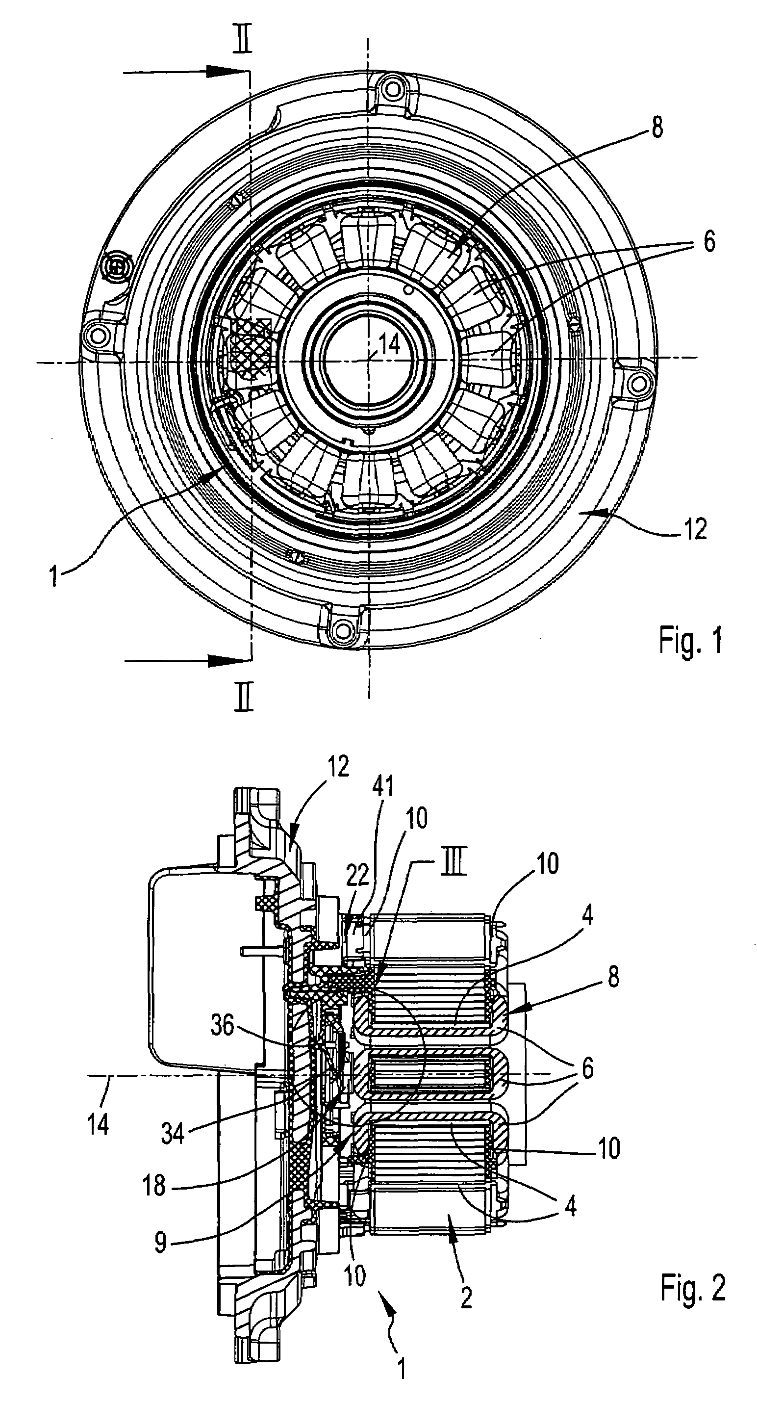
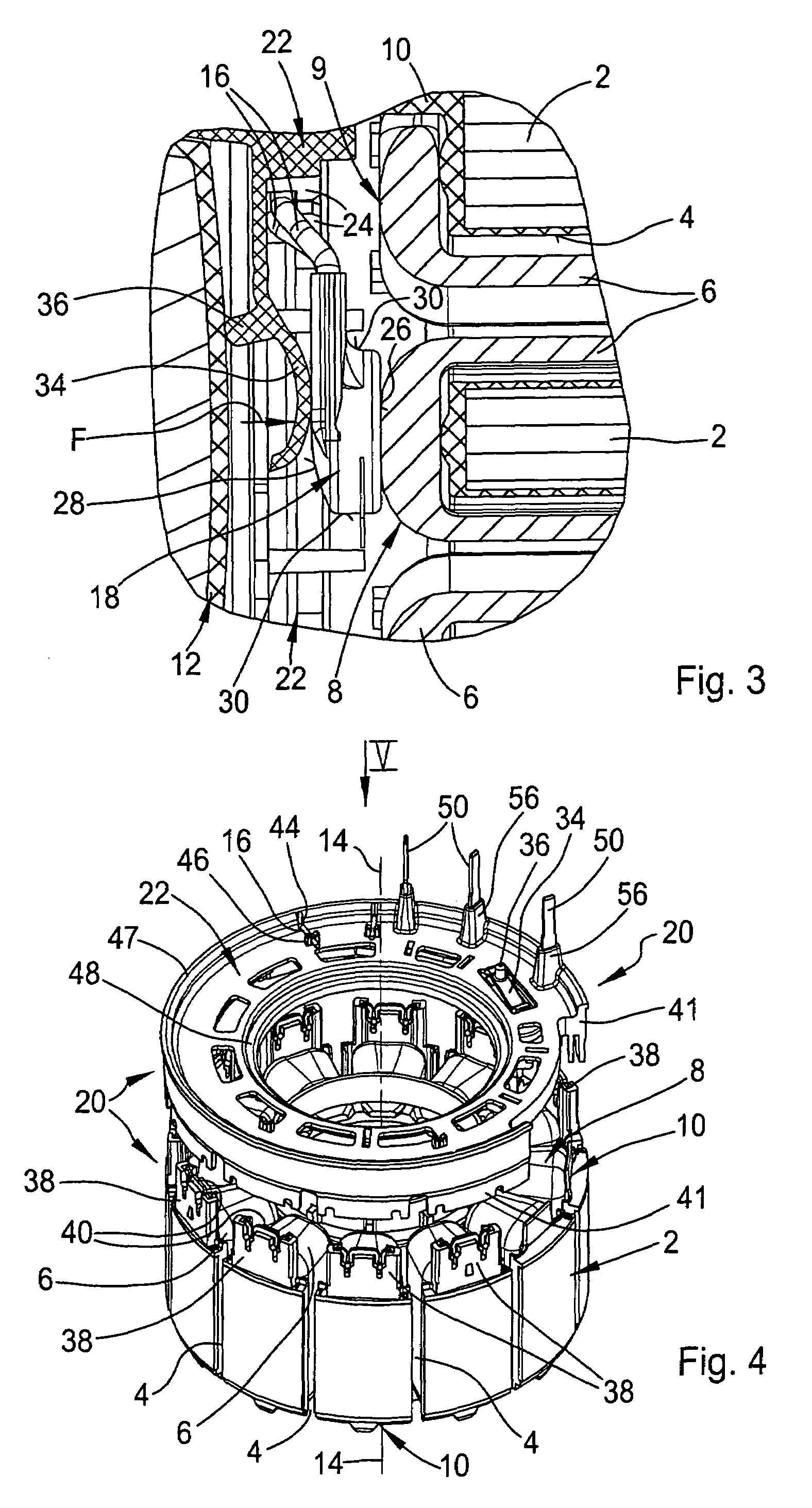
[0028]As can be seen initially in FIGS. 1 to 4, a stator 1 according to the invention comprises a laminated stator core 2 having stator slots 4, through which in each case winding elements 6 of a stator winding 8 extend. The laminated stator core 2 comprising layered sheet-metal laminates has an insulating plastic material injected around it at both of its end sides and within the slots. On the one hand, this serves the purpose of insulating the winding elements 6 within the stator slots 4 and, on the other hand, serves the purpose of insulating the so-called end winding 9 in the region of the end sides opposite the laminated stator core 2. This part of the insulation of the region on the end-winding side is in each case an end insulation 10.

[0029]The laminated stator core 2, which has had the stator winding 8 w...


PUM


Abstract

A stator for an electric motor, in particular for an external rotor motor, includes a laminated stator core which is provided with a stator winding and having a connecting arrangement, which is arranged on one end side in the region of an end winding of the stator winding, for the purpose of electrically connecting winding wire ends of the stator winding and connecting wires of a temperature monitor connected upstream of the stator winding. The connecting arrangement has an insulating switching disk which covers the region of the end winding, in particular in the form of a cap. The temperature monitor is held in the switching disk in an integrated manner such that, on the end-winding side, it rests between the Mater winding and the switching disk such that it is in thermally conductive bearing contact with said stator winding.

Description

CROSS REFERENCE TO RELATED APPLICATIONS[0001]This application claims priority to European patent application number 0 510 4339.6, filed May 23, 2005.FIELD OF THE INVENTION[0002]The present invention relates to a stator for an electric motor, in particular for an external rotor motor, having a laminated stator core which is provided with a stator winding and having a connecting arrangement. The connecting arrangement is positioned on one end side in the region of an end winding of the stator winding, for the purpose of electrically connecting winding wire ends of the stator winding and connecting wires of a temperature monitor connected upstream of the stator winding.BACKGROUND AND SUMMARY OF THE INVENTION[0003]A stator of the above general type is described in EP 0 993 095 A1 / B1. With this known stator, the laminated stator core has an insulating plastic compound injected around it at both of its end sides and within stator slots, through which the stator winding is wound, the plast...

Claims


Application Information

Patent Timeline
Patent Type & Authority Patents(United States)
IPC IPC(8): H02K3/50H02K11/00
CPCH02K3/522H02K11/0047H02K2203/03H02K11/25H02K3/48
Inventor BEST, DIETERZIERLEIN, RAINERKINZEL, ALEXANDERFIEDLER, ERICH
Owner EBM PAPST MULFINGEN GMBH & CO KG
Why Eureka
Try Eureka