Thermosyphon and method for producing it

a technology of thermosyphon and thermosyphon plate, which is applied in the direction of heat exchange apparatus, electric devices, solid-state devices, etc., can solve the problems of difficult and time-consuming manufacturing techniques, limited cooling efficiency of this type of thermosyphon plate,

Inactive Publication Date: 2005-03-17
SAPA
View PDF18 Cites 50 Cited by
  • Summary
  • Abstract
  • Description
  • Claims
  • Application Information

AI Technical Summary

Problems solved by technology

The micro channel heat pipes of the prior art is fabricated by difficult and time consuming manufacturing techniques.
The cooling efficiency of this kind of thermosyphon Is limited.

Method used


Image

  • Thermosyphon and method for producing it
  • Thermosyphon and method for producing it
  • Thermosyphon and method for producing it

Examples


example

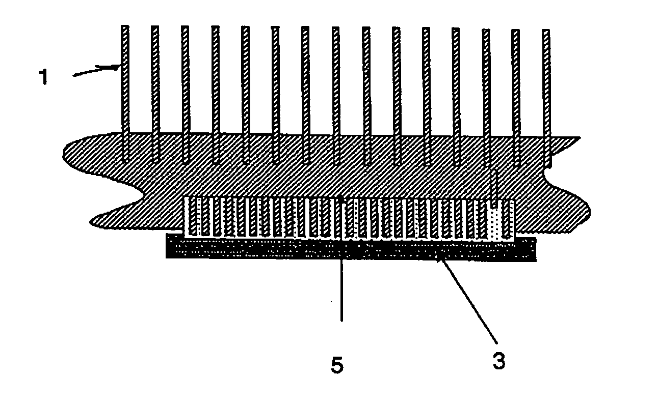
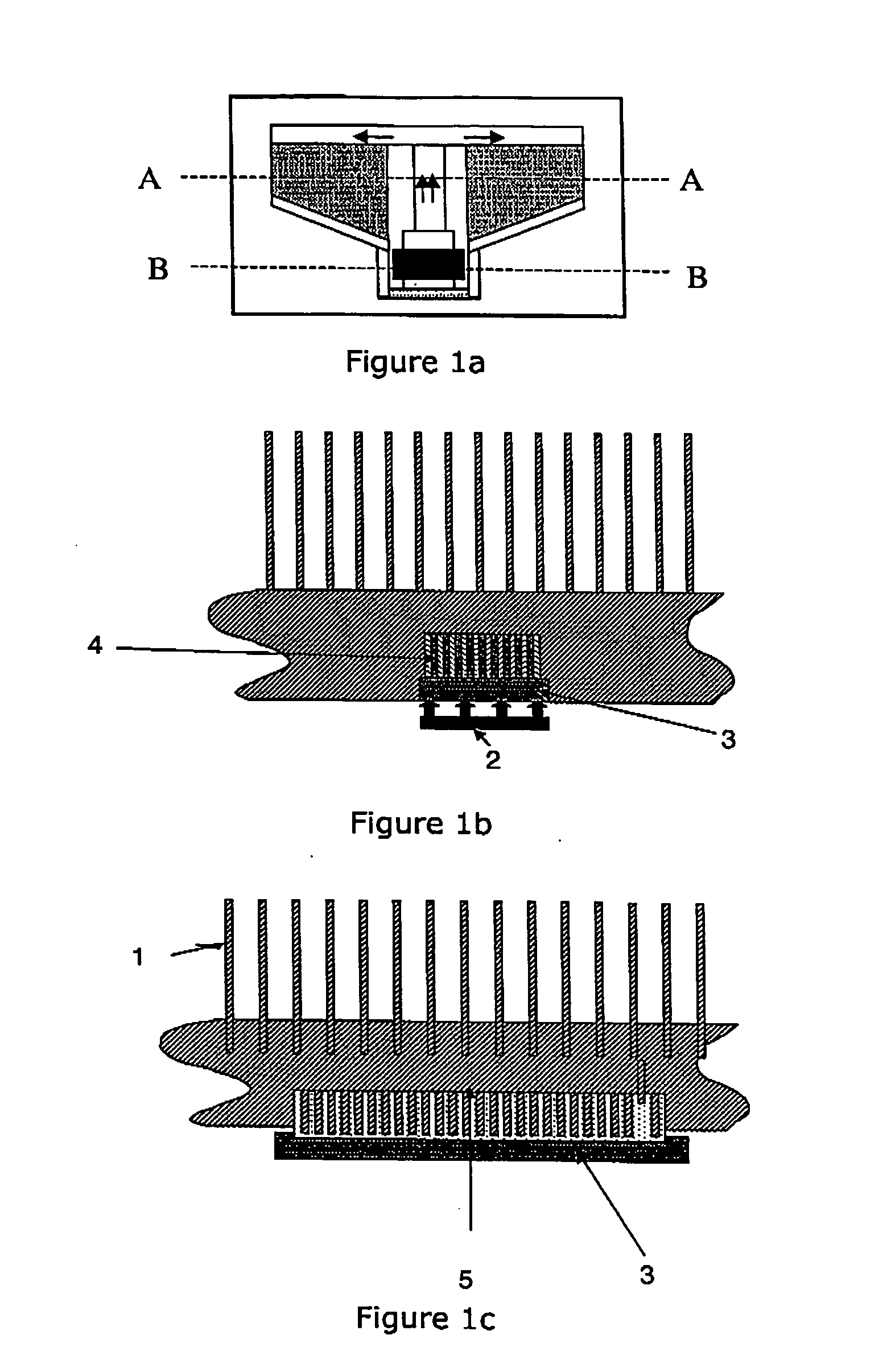
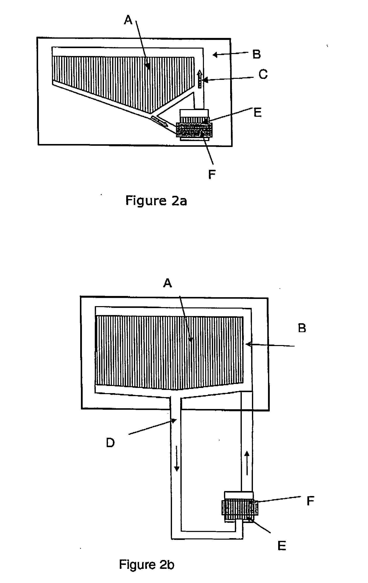
[0024] A lid is extruded from an aluminium billet so that a plate is formed having fins extending from one side along the centre of the plate. The fins extending beyond the area dedicated to the evaporator are removed by milling to form the evaporator section, E, according to FIG. 2a. A base is then extruded to form a plate having heat dissipating fins extending from one side. The flat side of the base is machined so that condenser channels, A, are formed in a pattern according to FIG. 2a as well as a cavity for the evaporator fins to fit into. The lid is joined to the base by traversing a friction stir welding tool along the joint (shown as the contour of the thermosyphon in FIG. 1a). When the lid and the base are joined a sealed chamber constituting a thermosyphon is formed inside the chamber. The evaporator is filled with liquid. The choice of working fluid is based upon the working temperature of the thermosyphon, and may be chosen according to the specific demands in each case....


PUM


Abstract

The present invention relates to thermosyphons, in particular for use in the cooling of electronic components. In a first embodiment a thermosyphon is manufactured by extruding a base (1) and milling a channel structure in the base to produce a plurality of fins (5) extending vertically from the base. A lid (3) comprising a number of fins (4) extending vertically from the lid is placed over the heat sink channel structure so that a thermosyphon of an expanding channel system is formed. In a second embodiment the evaporator and condenser sections are separated and connected by pipes. To form a leak proof seal between the lid and the base, joining is preferably done by friction stir welding. By providing an extruded thermosyphon, heat transfer is made more efficient than when junctions are used. The present invention provides a new way of efficiently manufacturing an integrated structure, while keeping the heat transfer of the structure high.

Description

TECHNICAL FIELD [0001] The present invention relates to thermosyphons, in particular for use in the cooling of electronic components. [0002] Thermal management is a key issue in the design of the electronic package. The proper design insures that the peak temperatures remain within a specified operating range to produce a reliable module. The main objective is to maintain the semiconductor device junction temperature below the maximum operating temperature of the module. Design challenges included in heat removal are higher circuit densities, close proximity of adjacent devices or components, low thermal conductivity substrates, inner layers of metal forming the interconnect, and the thermal resistance of heat sink systems. [0003] The purpose of any heat transfer design is to allow the flow of thermal energy from heat source to heat sink within the constraints of specified temperature levels. The current trend towards miniaturisation of electronic devices, greater functionality and ...

Claims


Application Information

Patent Timeline
Patent Type & Authority Applications(United States)
IPC IPC(8): F28D15/02F28D15/04H01L23/427
CPCF28D15/0233F28D15/0266F28F3/048H01L23/427H01L2924/0002F28F2255/16H01L2924/00
Inventor NORLIN, ANDERSTUOVINEN, SEPPOBENGTSSON, BOHOU, JIN
Owner SAPA
Why Eureka
Try Eureka