Antenna coil, and RFID-use tag using it, transponder-use antenna

a technology of rfid-use tag and antenna coil, which is applied in the direction of loop antennas with ferromagnetic cores, resonant antennas, instruments, etc., can solve the problems of excessive protruding antenna coils from articles, decreased q value, and inability to use, etc., to achieve high rigidity

Inactive Publication Date: 2006-08-08
MITSUBISHI MATERIALS CORP
View PDF12 Cites 82 Cited by
  • Summary
  • Abstract
  • Description
  • Claims
  • Application Information

AI Technical Summary

Benefits of technology

[0025]An object of the present invention is to provide an antenna coil having relatively high rigidity which can be used in a relatively high frequency.
[0026]Other object of the present invention is to provide an antenna coil in which a space which should be inserted between the antenna coil and an article is unnecessary such that a protrusion of the antenna coil from an article which is an object to be controlled can be more reduced than the conventional antenna coil.
[0027]In addition, an object of the present invention is to provide a tag antenna coil which can be formed quite thinly so as to be operated reliably while contacting the metal article closely. Also, an object of the present invention is to provide a tag antenna coil which is suitable for a mass production.

Problems solved by technology

Therefore, there has been a disadvantage that the antenna coil protrudes excessively from the article which is an object to be controlled.
However, if the frequency of the radio wave is as high as several MHz to several ten MHz, there has been a disadvantage in that an eddy current occurs in the amorphous sheet or the electromagnetic steel plate in the magnetic core member; thus, the Q value decreased.
There was a disadvantage in that an antenna coil disclosed in Japanese Unexamined Patent Application, First Publication No. 2000-48152 could not be used for a tag which is activated by a high frequency radio wave.
However, the sintered ferrite is fragile relatively.
In particular, if a sintered ferrite which is formed very thinly so as to be used for a magnetic core member so as to form a thin antenna coil, there may occur a crack on such a magnetic core member; thus, there is a problem in that an actually operable condition may be limited.
Therefore, there is a problem in that it is not possible to realize an object to reduce a protrusion of the antenna coil from an article which is an object to be controlled.
Therefore, an eddy current is generated on a metal part due to the magnetic flux which passes therethrough; thus, the eddy current generates an undesirable influence.
Therefore, there was a problem in that the antenna coil may not be operated properly.
Also, even if the antenna coil can be operated, the loss therein increases; thus, there was a problem in that an operable distance of the antenna coil may be shortened to a great extent.
Such a process for winding a conductive member 7 takes times and effort; thus, there has been a disadvantage from a productivity point of view.
If such an antenna coil is attached on a surface of an article, there has been a problem in that the antenna coil protrudes from the article to a great extent relatively.
Therefore, there has been a disadvantage in that such a process for winding a conductive member 7 is complicated relatively.
Also, an entire antenna coil may be thick relatively; thus, there has been a problem in that the antenna coil may protrude from the article if the antenna coil is attached on a surface of the article.
However, such a space is relatively thick in the above conventional transponder.
Thus, there has been a disadvantage in that the transponder protrude from an article which is an object to be controlled to a great extent.

Method used


Image

  • Antenna coil, and RFID-use tag using it, transponder-use antenna
  • Antenna coil, and RFID-use tag using it, transponder-use antenna
  • Antenna coil, and RFID-use tag using it, transponder-use antenna

Examples


example 1

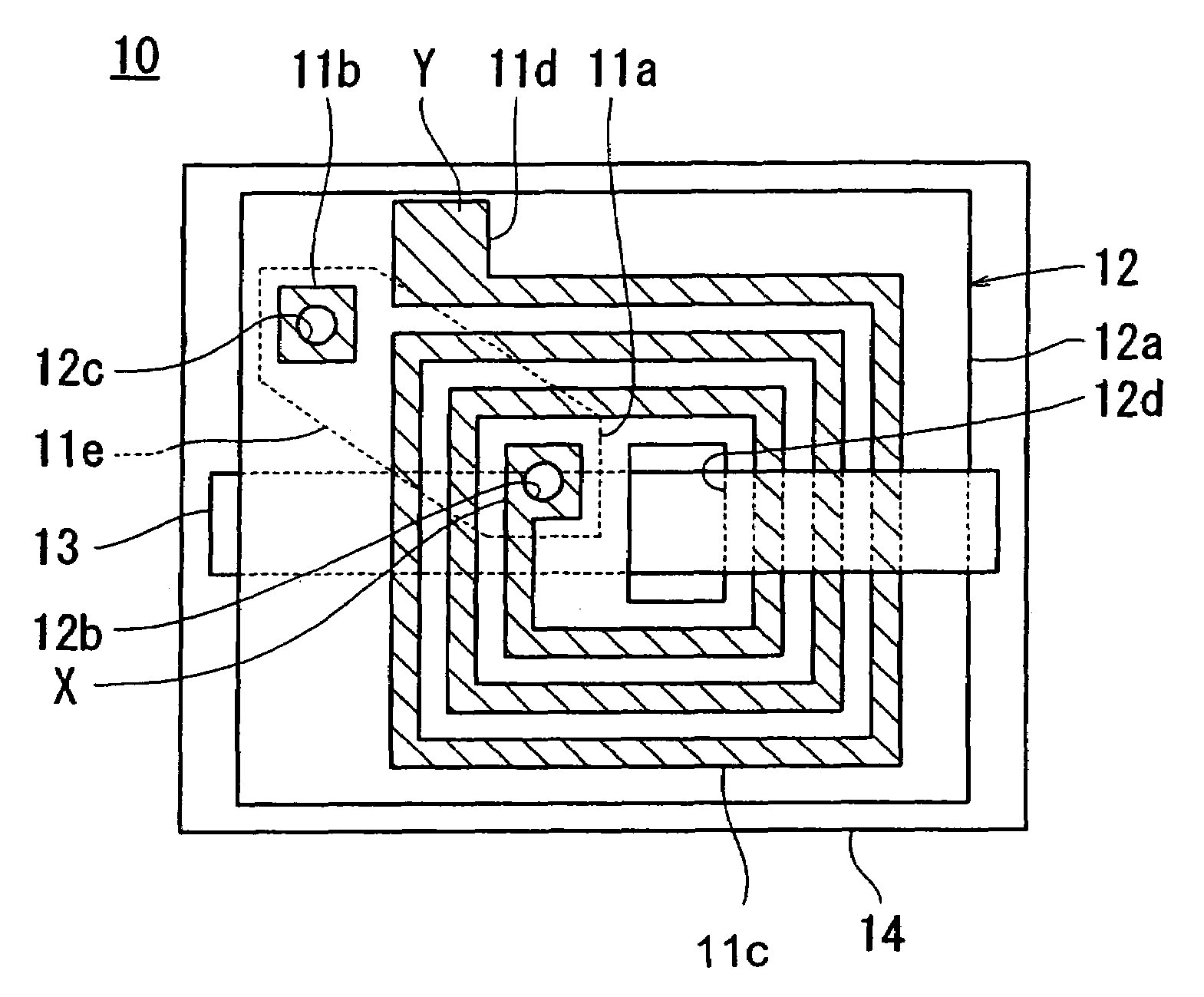
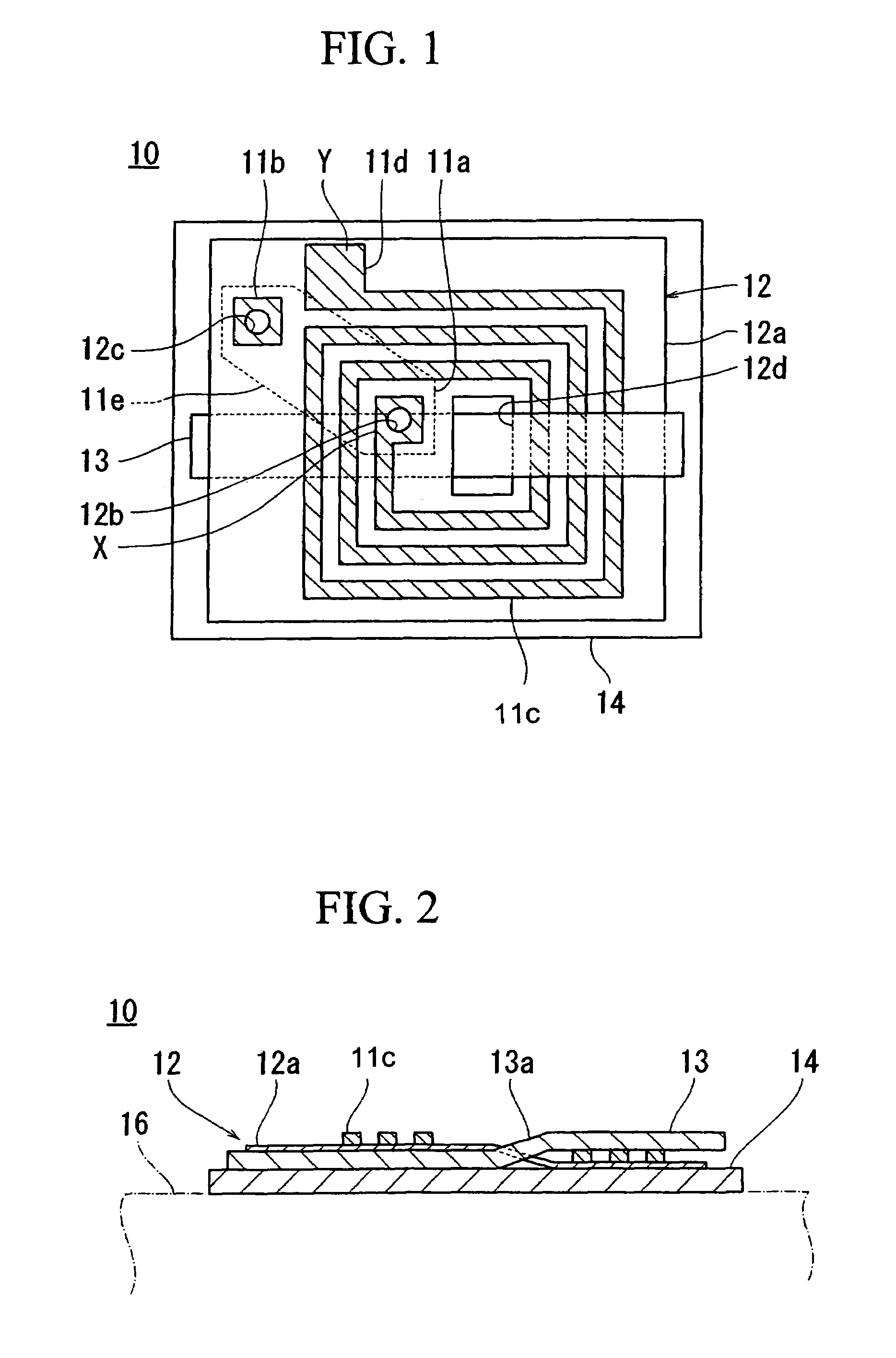
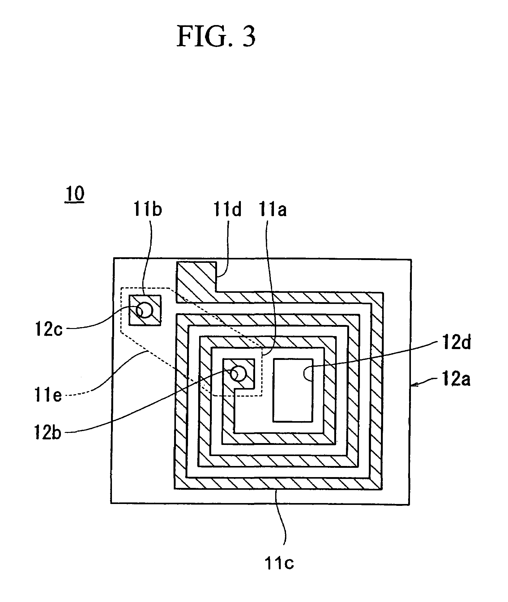
[0123]First, an air-core coil is formed on a main surface of an electrically insulating film. For the electrically insulating film, a polyimide film having 50 mm longitude and 50 mm latitude and 50 μm thickness is used. A copper film having 35 μm thickness is layered to be bonded on a main surface of the polyimide film so as to etch the copper film. By doing this, an air-core coil which is wound helically in a four-time rectangular manner is formed on a main surface of the polyimide film. The conductive member which forms the air-core coil is formed so as to have 0.8 mm width. An outer shape of the air-core coil is formed so as to have a dimension such as 18 mm×47 mm.

[0124]Next, a mixture of 92 weight % of a carbonyl iron powder and a nylon resin is injected into a mold. By doing this, a magnetic core member 13 which is formed by a composite member having 0.87 mm thickness and 35 mm×52 mm dimension is obtained. Consequently, a hole having 35 mm×1 mm of dimension is formed on an elec...

example 2

[0125]An air-core coil which is the same as that of the example 1 is formed on an electrically insulating film which is the same as the electrically insulating film of the example 1 by the same conductive member as that of the example 1 by the process which is the same as the process in the example 1. Also, a paint is prepared in which 70 weight % of amorphous flake, 10 weight % of acrylic resin, and 20 weight % of ethyl acetate as a solvent are mixed. The paint is applied and dried on an entire main surface of a film which is formed by a polyethylene terephthalate having 0.1 mm thickness. Thus, a magnetic coating having 0.1 mm thickness is obtained. A film on entire main surface of which the magnetic coating is formed is cut in to a dimension of 35 mm×60 mm with the magnetic coating. Thus, the magnetic core member 13 which is made of a magnetic coating which is formed by applying and drying the composite member is obtained. Consequently, a hole having 35 mm×1 mm of dimension is for...

example 3

[0153]As shown in FIGS. 4 and 5, a conductive member 112 is formed on a surface of the electrically insulating member 111 which is formed by an electrically insulating film. For the electrically insulating film, a polyimide film is used which has a dimension such as 50 μm thickness, and longitude and a latitude such as 65 mm×55 mm. A copper film having 35 μm is layered and bonded on a main surface of the polyimide film. A continuous conductive member 112a is formed on a surface of the polyimide film by etching the copper film such that the conductive member 112 has three winding forwarding sections 112a and three winding returning sections 112b both of which has 40 mm length are formed on a surface of the polyimide film alternatively with an interval of 10 mm. The conductive member 112 has 0.8 mm width.

[0154]After that, the first magnetic core member 113 having a dimension such as 1 mm thickness and longitude and a latitude such as 40 mm×20 mm is bonded on a back surface of the cond...


PUM


Abstract

An antenna coil includes an air-core coil wound helically in a plane and a plate magnetic core member inserted in the air-core coil to be approximately parallel with a plane of the air-core coil. The magnetic core member is formed by a soft magnetic metal, an amorphous or ferrite, or a composite member of a powder, flake and plastic, or rubber. The magnetic core member is formed by performing an injection molding operation or a compressing molding operation of the composite member. Alternatively, the magnetic core member is a magnetic coating formed by applying and drying the composite member. A non-magnetic conductive plate that has a conductivity is layered on a surface of the air-core coil through which the magnetic core member is inserted. The conductive plate is made of a copper, a copper alloy, an aluminum or an aluminum alloy having 0.01 to 2 mm thickness. The antenna coil is operated by relatively high frequency while it is rigid relatively.

Description

[0001]This application is a 371 of PCT / JP02 / 09955 filed Sep. 26, 2002.[0002]1. Technical Field[0003]The present invention relates to an antenna coil which is used for an identification tag in which an RFID (Radio Frequency Identification) technology or an EAS (Electronic Article Surveillance) technology is used.[0004]Also, the present invention relates to an antenna which is used for a transponder such as a tag or a reader / writer in which the EAS technology is used.[0005]More specifically, the present invention relates to a transponder antenna which is provided with a helix coil so as to be attached to an article.[0006]2. Background Art[0007]Conventionally, for a tag in which the RFID technology or the EAS technology is used, an identification tag is known to which an IC chip in which an information is stored and a condenser for resonation are connected to an antenna coil electrically. In such an identification tag, it has been know that the tag is activated by transmitting a radio ...

Claims


Application Information

Patent Timeline
Patent Type & Authority Patents(United States)
IPC IPC(8): H01Q7/08G06K19/07B42D15/10G06K19/077G08B13/24H01Q1/22H01Q1/38H01Q7/00H01Q7/06H01Q9/27H01Q11/04
CPCG06K19/0726G06K19/07749G06K19/07771G06K19/07779G06K19/07783H01Q9/27H01Q1/2225H01Q1/38H01Q7/00H01Q7/06H01Q1/22
Inventor ENDO, TAKANORIYAHATA, SEIROUTSUCHIDA, TAKASHIYONEZAWA, TADASHI
Owner MITSUBISHI MATERIALS CORP
Why Eureka
Try Eureka