Receptacle Positioning Apparatus

a positioning apparatus and receptacle technology, applied in the direction of manufacturing tools, furniture parts, and refuse gathering, can solve the problems of waste receptacles slipping or moving in a direction away from users, failing to address waste receptacles, and leaving a mark or other damage to adjacent walls, so as to achieve the effect of discouraging skewing of the body

Inactive Publication Date: 2008-06-12
MCGEE JOHN
View PDF19 Cites 7 Cited by
  • Summary
  • Abstract
  • Description
  • Claims
  • Application Information

AI Technical Summary

Benefits of technology

[0010]In this light, the invention provides an apparatus that maintains the waste receptacle at a distance from the adjacent wall to permit the receptacle to open properly without any portion of the waste receptacle impacting or damaging the wall.
[0011]The invention prevents a waste receptacle from sliding toward an adjacent wall.
[0012]In one embodiment of the invention, an apparatus is provided for positioning a movable object with respect to an immovable object. The apparatus includes a body defining a top surface and a bottom surface. A first surface extends between the top surface and the bottom surface for engaging the movable object. A second surface extends between the top surface and the bottom surface for engaging the immovable object. The second surface is opposed to the first surface. At least first and second contact points are defined by the first surface and at least third and fourth contacts points are defined by the second surface. The first and second contact points are separated from one another by a first distance. The third and fourth contact points are separated from one another by a second distance. The first distance is less than or equal to the second distance, thereby discouraging skewing of the body when forces of disproportionate magnitudes are applied to the first and second contact points.

Problems solved by technology

Each time a user applies pressure to the step-pedal, however, the waste receptacle has a tendency to move or slide in a direction away from the user.
As should be appreciated by the typical user of these types of waste receptacles, when the lid of the receptacle opens and the receptacle is very near to an adjacent wall, the lid may hit the adjacent wall, leaving a mark or otherwise damaging the adjacent wall.
These failings with respect to waste receptacles remain unaddressed.

Method used


Image

  • Receptacle Positioning Apparatus
  • Receptacle Positioning Apparatus
  • Receptacle Positioning Apparatus

Examples


first embodiment

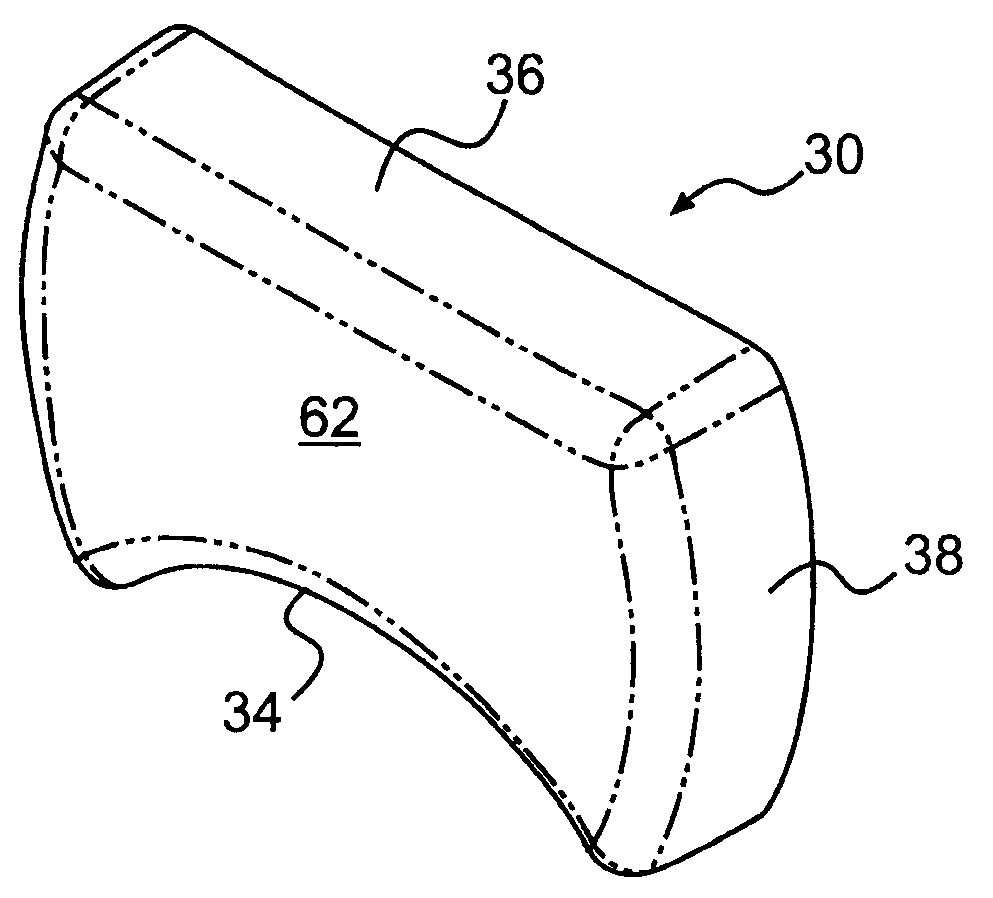
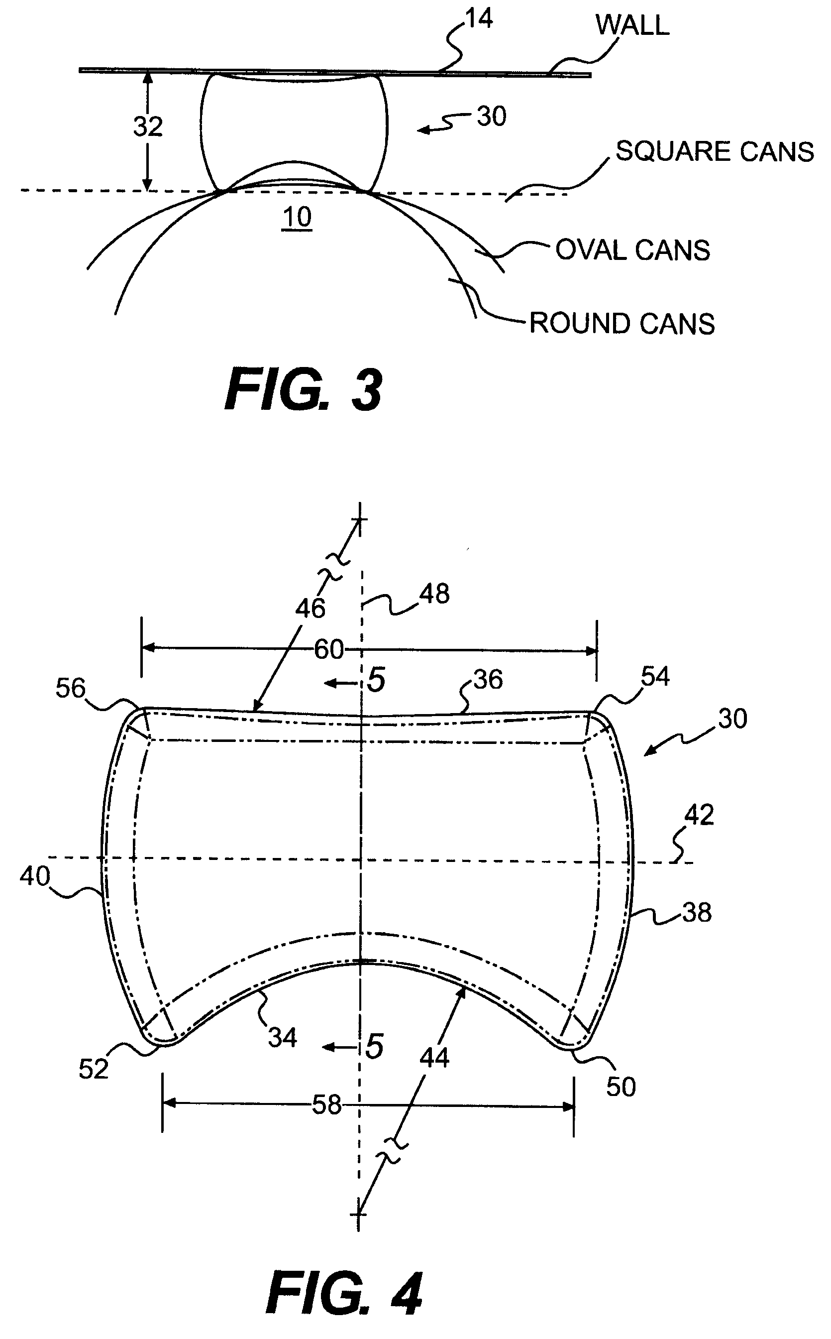
[0056]FIG. 4 is a top plan view of the apparatus 30 of the invention. This embodiment is the same as the apparatus 30 illustrated in FIG. 3. The apparatus 30 includes a first side 34 and a second side 36, which are opposed to one another. The apparatus 30 also includes a third side 38 and a fourth side 40, which are opposed to one another.

[0057]As is apparent from FIG. 4, the first side 34 curves inwardly toward a first centerline 42 between the first side 34 and the second side 36. In FIG. 4, the first surface has a continuous curve that is defined by a first radius of curvature 44. Similarly, the second surface 36 also curves inwardly toward the first centerline 42, albeit to a smaller extent than the first surface 34. As with the first surface 34, the second surface has a constant curvatures defined along a second radius of curvature 46. As should be appreciated by those skilled in the art, the illustrated first and second radii of curvatures 44, 46 are not required to practice t...

fourth embodiment

[0079]FIG. 13 illustrates the invention. This embodiment is a further variation of the apparatus 66. Here, the apparatus is designated by the reference number 102. The apparatus 102 differs from the apparatus 66 in that projections 104 have been added to the bottom surface 94. The projections 104 are added for instances where the waste receptacle 10 is placed in a carpeted environment. The projections 104 are intended to engage the piles of the carpeting to further secure the apparatus 102 in place. While three projections 104 are illustrated, a greater or a fewer number may be employed without departing from the scope of the invention.

[0080]Additional embodiments of the invention will now be discussed in connection with FIGS. 14-29.

fifth embodiment

[0081]FIG. 14 illustrates the invention. In this embodiment, the apparatus 106 includes a first side 108 and a second side 110. The first side 108 defines a first contact point 112 and a second contact point 114. The second side 110 defines a third contact point 116 and a fourth contact point 118. As in the prior embodiments, the first and second contact points 112, 114 are intended to engage a waste receptacle 10. As in the prior embodiments, the third and fourth contact points 116, 118 are intended to engage an immovable object such as the wall 14. In this embodiment, the distance between the first and second contact points 112, 114 is less than the distance between the third and fourth contact points 116, 118.


PUM


Abstract

An apparatus for positioning a movable object with respect to an immovable object is described. The apparatus includes a body with a top surface, a bottom surface, a first surface extending between the top surface and the bottom surface for engaging the movable object, and a second surface extending between the top surface and the bottom surface for engaging the immovable object, the second surface being opposed to the first surface. At least first and second contact points are defined by the first surface. At least third and fourth contacts points are defined by the second surface. The first and second contact points are separated from one another by a first distance and the third and fourth contact points are separated from one another by a second distance. The first distance is less than or equal to the second distance.

Description

CROSS-REFERENCE(S) TO RELATED APPLICATION(S)[0001]This patent application relies for priority on U.S. Provisional Patent Application Ser. No. 60 / 874,275, entitled “Trash Can Spacer,” which was filed on Dec. 12, 2006, the contents of which are incorporated herein by reference.FIELD OF THE INVENTION[0002]The invention concerns an apparatus that cooperates with a receptacle, such as a waste receptacle or garbage can. The apparatus positions the waste receptacle a predetermined distance from an immovable obstacle, such as a wall.DESCRIPTION OF THE RELATED ART[0003]Waste receptacles, including trash cans, are available to consumers in a wide variety of different styles.[0004]One common style of waste receptacle or garbage can is commonly referred to as a step-pedal type. For this particular waste receptacle, the user steps on a pedal, typically on the front of the waste receptacle. Application of pressure to the pedal causes the top of the receptacle to open.[0005]Each time a user applie...

Claims


Application Information

Patent Timeline
Patent Type & Authority Applications(United States)
IPC IPC(8): B65F1/14A47B97/00
CPCA47B97/00Y10T16/95B65F1/141Y10T428/8305
Inventor MCGEE, JOHN
Owner MCGEE JOHN
Why Eureka
Try Eureka