Eureka AIR delivers breakthrough ideas for toughest innovation challenges, trusted by R&D personnel around the world.

Method for measuring variable bandwidth wireless channel and transmitter and receiver therefor

Active Publication Date: 2008-06-12
ELECTRONICS & TELECOMM RES INST
View PDF14 Cites 12 Cited by
  • Summary
  • Abstract
  • Description
  • Claims
  • Application Information

AI Technical Summary

Benefits of technology

[0019]The conventional technology has a problem about measuring a wireless channel of

Problems solved by technology

That is, when the analog intermediate frequency method is adopted in the receiving part, the receiving signal is converted into an In-phase signal (I signal) and a quadrature-phase signal (Q signal) of a baseband from an intermediate frequency band in a form of an analog signal, distortion may occur due to I / Q mismatch in the above procedure.
However, since over-sampling increases, a D / A operation speed needs to be fast.
As described above, since the case that the measurement bandwidth is fixed is considered in the conventional wireless channel measurement method, there is a problem that a plurality of wireless channel measurement transmitters and receivers are required in order to measure the wireless channel of a plurality of bandwidths.

Method used


Image

  • Method for measuring variable bandwidth wireless channel and transmitter and receiver therefor
  • Method for measuring variable bandwidth wireless channel and transmitter and receiver therefor
  • Method for measuring variable bandwidth wireless channel and transmitter and receiver therefor

Examples


Embodiment Construction

[0034]The advantages, features and aspects of the invention will become apparent from the following description of the embodiments with reference to the accompanying drawings, which is set forth hereinafter. Therefore, those skilled in the field of this art of the present invention can embody the technological concept and scope of the invention easily. In addition, if it is considered that detailed description on a related art may obscure the points of the present invention, the detailed description will not be provided herein. The preferred embodiments of the present invention will be described in detail hereinafter with reference to the attached drawings.

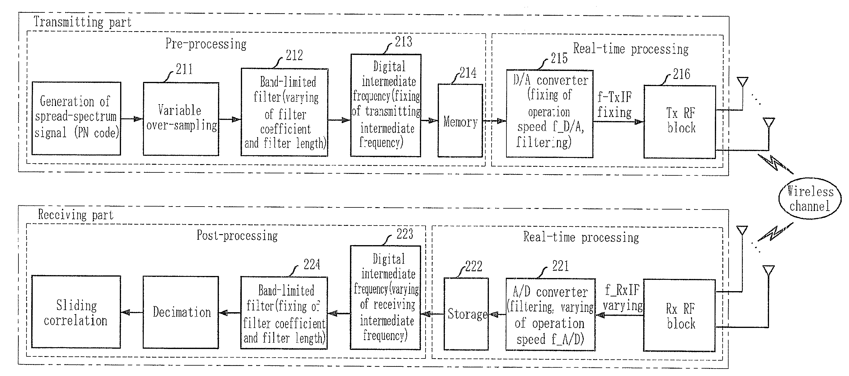
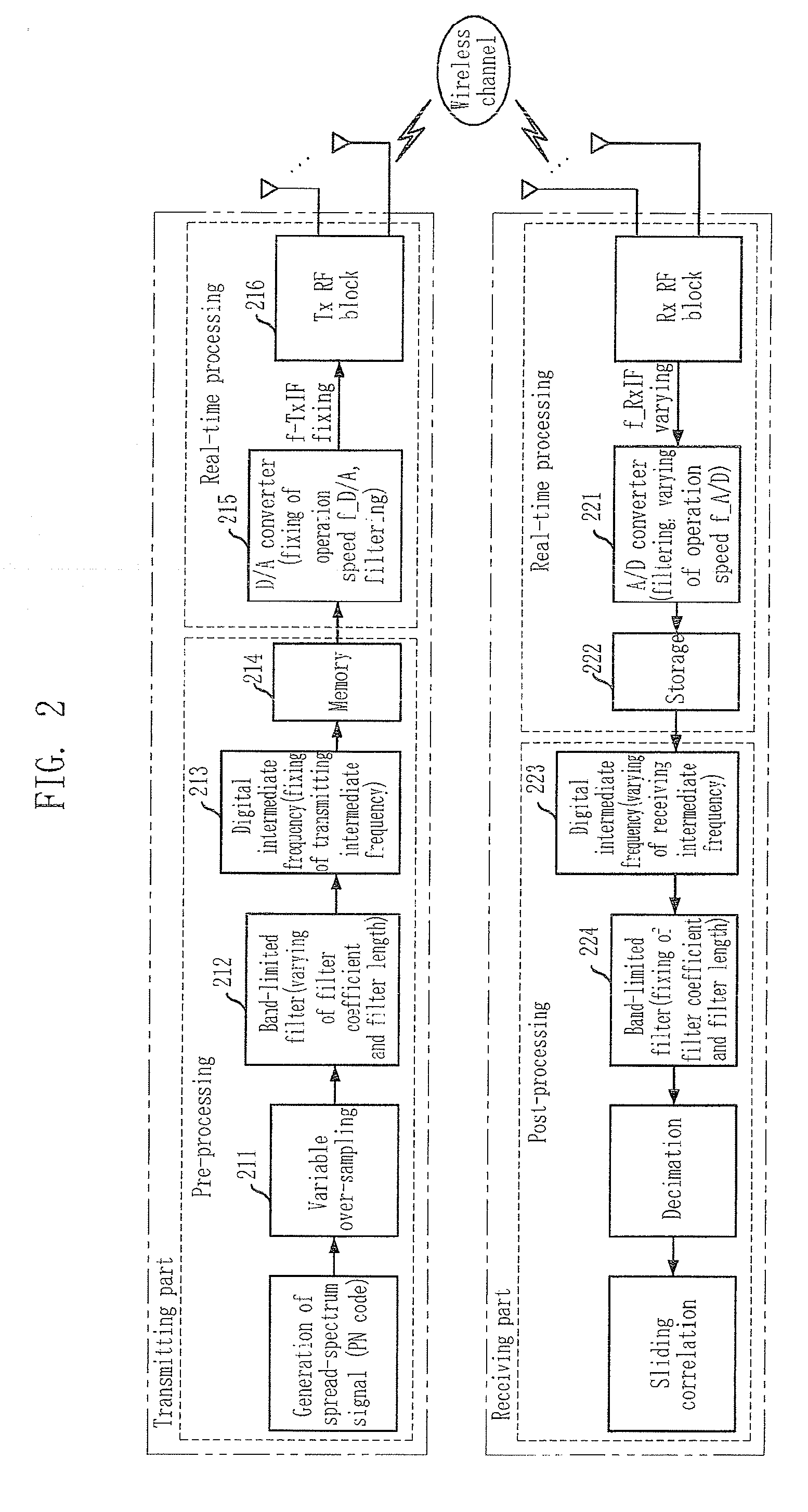
[0035]FIG. 2 shows a transmitter and a receiver for measuring a variable bandwidth wireless channel in accordance with an embodiment of the present invention.

[0036]Referring to FIG. 2, although a case that a Pseudo Random Binary Sequence (PRBS) method using a pseudo noise (PN) code as an original sequence for measurement is applie...


PUM


Abstract

Provided are a method for measuring a variable bandwidth wireless channel, and a transmitter and a receiver therefor. The transmitter, includes: a pre-processing unit for performing variable over-sampling and band-limited filtering on an original sequence for measuring the wireless channel according to a pre-determined digital-to-analog (D / A) operation speed and measurement bandwidth, and creating and storing a probing sequence whose frequency is up-converted into a fixed transmitting intermediate frequency; and a real-time processing unit for transmitting a probing signal that the stored probing sequence is converted according to the D / A operation speed to the wireless channel.

Description

CROSS-REFERENCE(S) TO RELATED APPLICATIONS[0001]The present invention claims priority of Korean Patent Application Nos. 10-2006-0124918 and 10-2007-0118559 filed on Dec. 8, 2006 and Nov. 20, 2007, respectively, which are incorporated herein by reference.BACKGROUND OF THE INVENTION[0002]1. Field of the Invention[0003]The present invention relates to a method for measuring a variable bandwidth wireless channel, and a transmitter and a receiver therefor; and, more particularly, to a method for measuring variable bandwidth wireless channel by creating a variable bandwidth signal by fixing a digital-to-analog (D / A) operation speed and varying over-sampling according to a measurement bandwidth in a transmitting part, and acquiring a variable bandwidth signal by varying a receiving intermediate frequency and an analog-to-digital (A / D) operation speed according to a measurement bandwidth in a receiving part, and a transmitter and a receiver therefor.[0004]This work was supported by the IT R...

Claims


Application Information

Patent Timeline
IPC IPC(8): H04B17/00
CPCH04L1/20H04B17/00H04W24/00
Inventor LEE, SUNG-JUNKWON, HEON-KOOKKIM, MYUNG-DONCHUNG, HYUN-KYULEE, KWANG-CHUN
Owner ELECTRONICS & TELECOMM RES INST
Why Eureka
Eureka Blog
Learn More