

Rotors having flow-modifying members for use in rotary engines
a technology of rotary engines and rotors, which is applied in the direction of liquid fuel engines, rotary piston liquid engines, machines/engines, etc., can solve the problems of limiting flame propagation and reducing the amount of compressed fuel/air mixture available for combustion
- Summary
- Abstract
- Description
- Claims
- Application Information
AI Technical Summary
Benefits of technology
Problems solved by technology
Method used
Image

Examples
Embodiment Construction
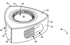
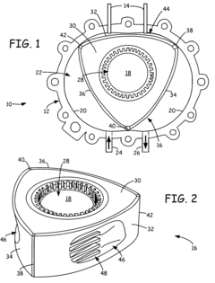
[0023]FIG. 1 is a front schematic illustration of engine 10. Engine 10 is a rotary internal combustion engine that includes housing 12, ignition sources 14, rotor 16, and output shaft 18. Housing 12 includes inner surface 20, which defines epitrochoid-shaped rotor chamber 22. Housing 12 also includes intake port 24, for drawing a fuel / air mixture into rotor chamber 22, and exhaust port 26, for emitting exhaust gases from rotor chamber 22.
[0024]In an alternate embodiment, one or both of intake port 24 and exhaust port 26 are located in an end wall of housing 12. In a further alternate embodiment, engine 10 is a fuel injected engine, in which intake port 24 draws air into rotor chamber 22, and the compressed fuel / air mixture is created by injecting fuel directly into combustion chamber 44, which is the region of rotor chamber 22 proximate ignition sources 14 and in which combustion occurs. Alternatively, fuel is injected into another region of rotor chamber 22, as defined in another l...
PUM
 Abstract
Description
Claims
Application Information