Method and System for Dynamic, Luminance-Based Color Contrasting in a Region of Interest in a Graphic Image

a dynamic, luminance-based color contrast and region-of-interest technology, applied in the field of computer systems, can solve the problems of increasing the amount of background image that is being covered by the foreground image element, user difficulty in working with an image, and increasing the amount of background image that is being obscured by the background image, so as to reduce the amount of background image obscured, increase the contrast, and soften the edges of the foreground image

Active Publication Date: 2008-06-19
ADOBE SYST INC
View PDF7 Cites 53 Cited by
  • Summary
  • Abstract
  • Description
  • Claims
  • Application Information

AI Technical Summary

Benefits of technology

[0008]Dynamic foreground images, such as cursors, bounding lines, shapes, and text may be displayed over an image by selecting the actual color values for the individual pixels of the foreground image to have high contrast in comparison to the surrounding background pixels. In order to select high-contrast colors, the background pixels with which the foreground pixels should contrast may first be converted from a non-luminance-isolating color space, such as a red-green-blue (RGB) color space, to a luminance isolating color space, such as YUV, HSL, or the like. In general, graphics hardware systems, such as graphics processors (GPUs) work with pixel color information in the non-luminance-isolating color space. Only pixels around and behind where the foreground image will be displayed may be converted, according to one embodiment. By converting the pixel information into a luminance isolating color space, the luminance or brightness of pixels can be adjusted (thereby adjusting the contrast between the foreground and background pixels) without cause unnecessary color shifts. As noted above, dynamic foreground images, such as cursors, are traditionally drawn using an XOR drawing mode that allows the same drawing function to both draw and erase the foreground image. However, XOR-based cursor drawing frequently causes color shifts that may interfere with the overall look of the image and that may also cause a user difficulty when working with an image, such as in a graphics or image drawing application.
[0011]The pixel information may then be converted back into the non-luminance-isolating color space, according to some embodiments. The pixel information of the foreground image may then be combined, composited or blended with the background image to display the foreground image. The blending may be performed using alpha information for the foreground and / or background images. Such blending may result in a partially transparent foreground image in some embodiments. Additionally, the alpha blending may result in anti-aliasing edge pixels of the foreground image. Such anti-aliasing may make the final display of the foreground image more pleasing to the eye, such as by removing jagged and / or blocky patterns in the image. Additionally, such anti-aliasing may help minimize the amount of the background image obscured by the foreground image.

Problems solved by technology

However, XOR-based cursor drawing frequently causes color shifts that may interfere with the overall look of the image and that may also cause a user difficulty when working with an image, such as in a graphics or image drawing application.
However, using such a double edge may increase the amount of the background image that is being covered by the foreground image element.
However, XOR-based cursor drawing frequently causes color shifts that may interfere with the overall look of the image and that may also cause a user difficulty when working with an image, such as in a graphics or image drawing application.
Additionally, the alpha blending may result in anti-aliasing edge pixels of the foreground image.

Method used


Image

  • Method and System for Dynamic, Luminance-Based Color Contrasting in a Region of Interest in a Graphic Image
  • Method and System for Dynamic, Luminance-Based Color Contrasting in a Region of Interest in a Graphic Image
  • Method and System for Dynamic, Luminance-Based Color Contrasting in a Region of Interest in a Graphic Image

Examples


Embodiment Construction

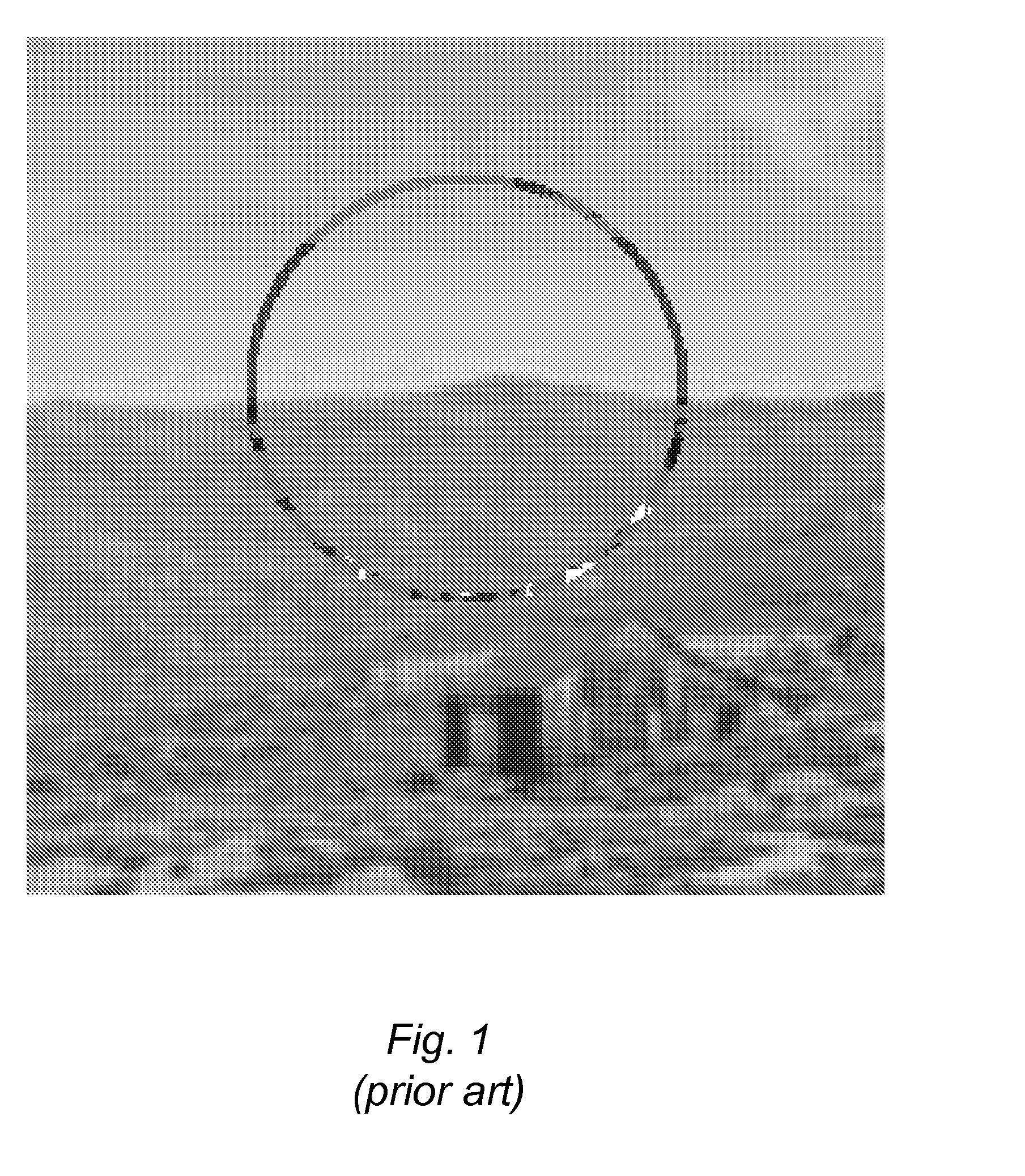
[0018]As described above, traditionally cursors and other dynamic foreground images are drawing using an XOR drawing mode. FIG. 1 is an image illustrating a circle drawn over a landscape background using an XOR drawing mode, according to the prior art. As can be seen in FIG. 1, the XOR drawing may result in color changes or shifts depending upon the exact color of the background and foreground at any particular pixel. While the XOR drawing illustrated in FIG. 1 may result in contrasting colors for the circle, the color changes from one area of the circle to another may cause the overall image to be visually disturbing, not pleasing to the eye, or even wrong. Such color shifts (also called chroma shifts or chroma crawling) may even interfere with a user's perception of the colors in the background image. For example, if a user is adjusting the colors of the background image the cursor used to select pixels of the background image for adjustment may include various colors and color sh...


PUM


Abstract

Foreground images, such as cursors, may be displayed over an image by selecting individual pixel colors to contrast with surrounding background pixels. The background pixels in, around and behind the foreground image may be converted from a red-green-blue (RGB) color space to a luminance isolating color space, such as YUV, HSL or the like. The converted pixel information may be copied, stored, or drawn into a separate compositing window. After converting to the luminance isolating color space, the luminance values of the pixels may be adjusted to increase the contrast between the foreground image and the background image. Portions of the foreground image may also be blurred, such as by applying a Gaussian or box blur, such as to soften the edges. The pixel information may then be converted back into the RGB color space and blended with the background information using alpha information for the foreground and background images.

Description

BACKGROUND[0001]1. Field of the Invention[0002]The present invention is directed to computer systems. More particularly, it is directed to graphical image processing.[0003]2. Description of the Related Art[0004]Traditionally, dynamic foreground image elements, such as cursors or user-defined bounding lines, are drawn using an XOR drawing mode that allows the same drawing function to both draw and erase the foreground image. XOR is a bitwise logical operation on two operands that results in a logical value of true if and only if one of the operands, but not both, has a value of true. The XOR operation is performed over each bit in the operands. Performing the same XOR operation on the same operands twice results in the original operands. Thus, when a cursor is drawn using an XOR mode, that cursor may be erased by drawing the same cursor again in the same location. When drawing foreground images using XOR, a foreground image is typically drawn into the frame buffer and therefore chang...

Claims


Application Information

Patent Timeline
Patent Type & Authority Applications(United States)
IPC IPC(8): G09G5/02
CPCG09G5/02G09G2340/06G09G5/377G09G5/363
Inventor HARRIS, JERRY G.KRISHNASWAMY, ARAVINDBYER, SCOTT
Owner ADOBE SYST INC
Why Eureka
Try Eureka