Handheld printer and method of operation

a portable printer and hand-held technology, applied in the field of printing devices, can solve the problems of limited image printing, significant limitations of hand-held printers, limited image printing, etc., and achieve the effect of increasing ability and rigidity and strong structur

Active Publication Date: 2008-06-19
RICOH KK
View PDF20 Cites 82 Cited by
  • Summary
  • Abstract
  • Description
  • Claims
  • Application Information

AI Technical Summary

Benefits of technology

[0008]The present invention overcomes the deficiencies and limitations of the prior art by providing a handheld portable printer and a method of operation. In one embodiment, the handheld portable printer includes a top member, a front member, a bottom member and a handle that are joined together to form a generally O-shaped device. The top member defines a hole through which a scroll dial protrudes and is adapted to support a retractable display on its top surface. The front member provides a more rigid and strong structure, provides an area for storing consumables and the battery and houses a projector to project an image on the print surface of the image to be printed. The bottom member tapers outward to provide increased ability as the handheld printer i...

Problems solved by technology

Most often such printers have a housing for holding the print head in a fixed orientation and complex paper handling trays and mechanisms to feed the print media past the print head and render the printed output.
However, existing hand-held printers have significant limitations.
For many existing hand-held printers, the size of the image that they are able to print is severely limited.
For example, some prior art printers are able to print only while they are stationary, and thus, are limited to printing images less than or equal to the printer itself or the print head, which in either case is less that a few inches square.
This also makes the printer bulky and diffi...

Method used


Image

  • Handheld printer and method of operation
  • Handheld printer and method of operation
  • Handheld printer and method of operation

Examples


Embodiment Construction

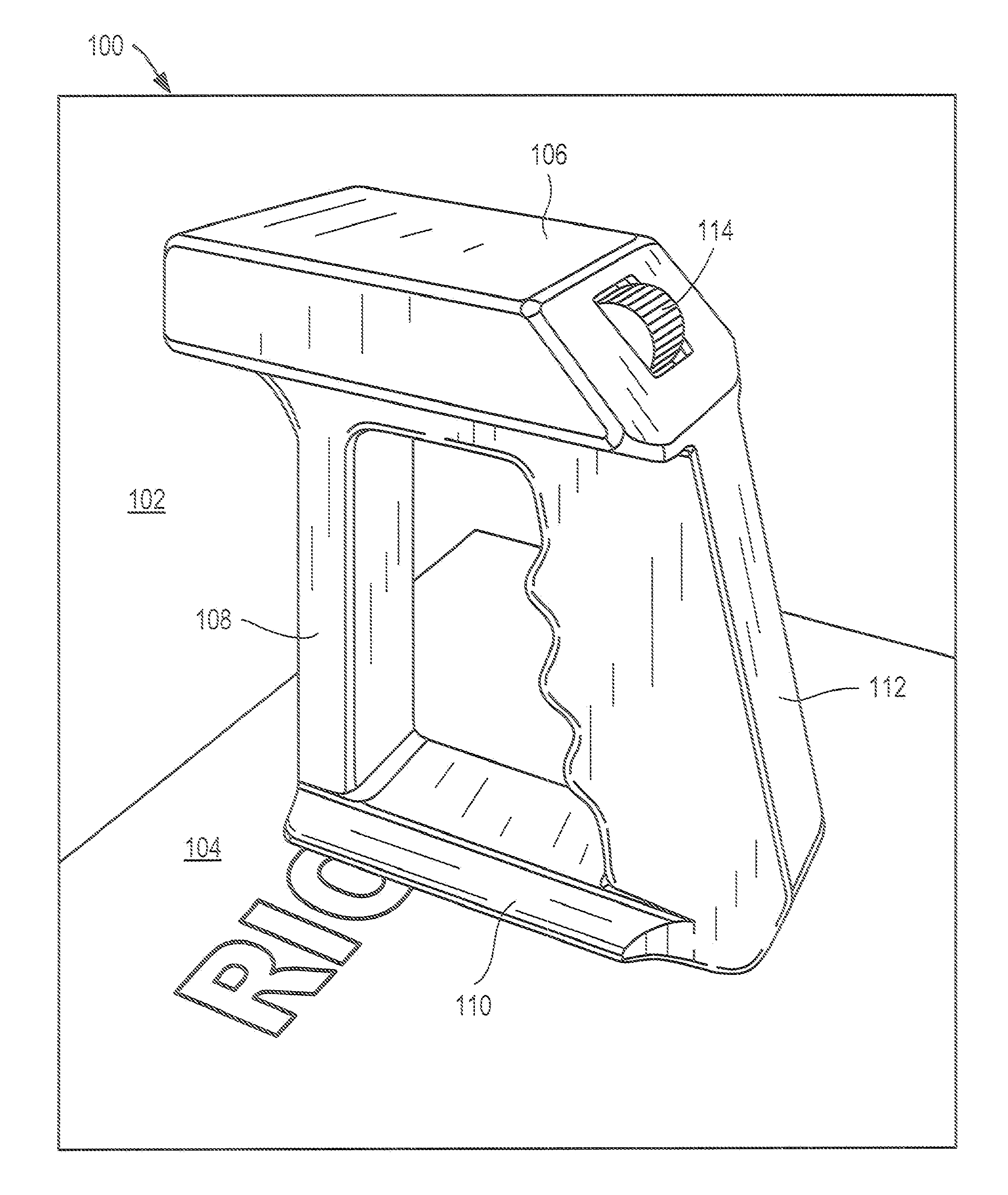
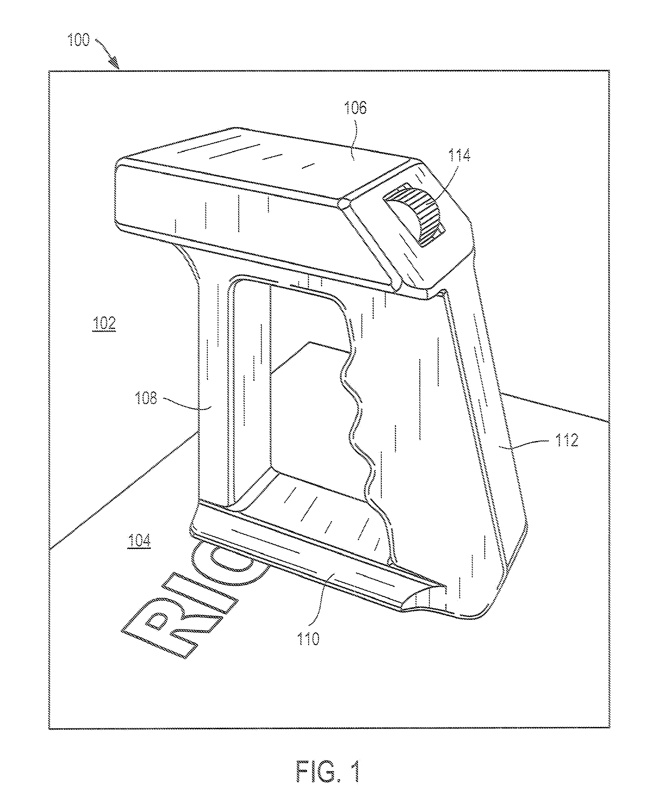
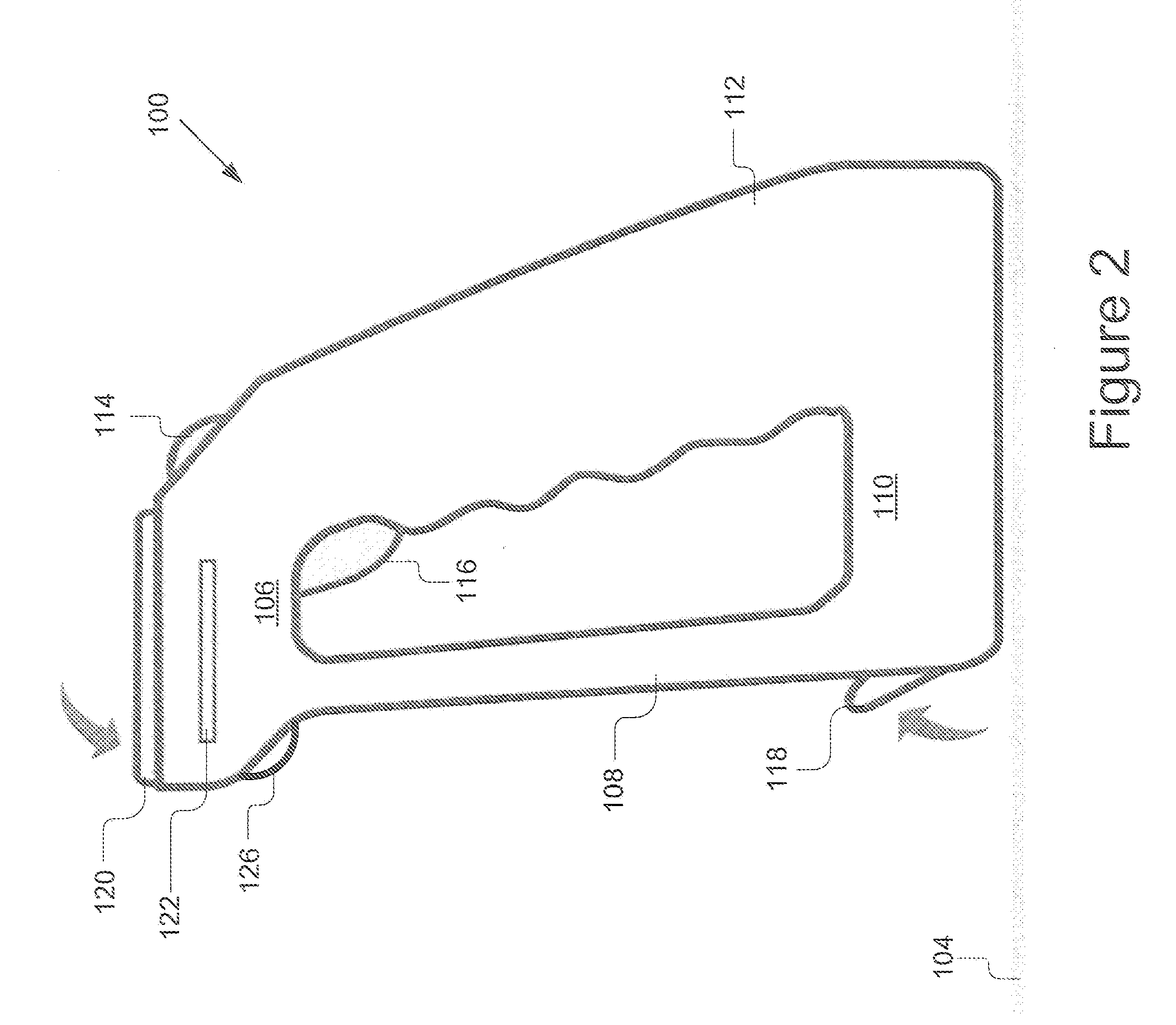
[0020]A handheld printer and a method for using same are described. In the following description, for purposes of explanation, numerous specific details are set forth in order to provide a thorough understanding of the invention. It will be apparent, however, to one skilled in the art that the invention can be practiced without these specific details. In other instances, structures and devices are shown in block diagram form in order to avoid obscuring the invention. For example, the present invention is described primarily with reference to printing documents for reading. However, the present invention applies to any type of printing including electronic circuits, partially invisible printing for marking and various other printing techniques.

[0021]Reference in the specification to “one embodiment” or “an embodiment” means that a particular feature, structure, or characteristic described in connection with the embodiment is included in at least one embodiment of the invention. The a...


PUM


Abstract

A handheld portable printer includes a top member, a front member, a bottom member and a handle that are joined together to form a generally O-shaped device. The top member defines a hole through which a scroll dial protrudes and is adapted to support a retractable display on its top surface. The front member provides an area for storing consumables, a battery, and houses a projector to project an image on the print surface of the image to be printed. The bottom member houses optical sensors to detect and measure movement of the handheld printer; and a print head for outputting ink on the print surface. The handle provides additional buttons for inputting command to lock an image or begin printing, and in one embodiment housing electronics for control and projection of the image to be printed, providing user feedback, and communicating with other devices. The present invention also includes a number of novel methods including: a method for printing an image with a handheld printer, a method for projecting an image to be printed, and a method for registering a location of a printer and portions of a printed image.

Description

BACKGROUND OF THE INVENTION[0001]1. Field of the Invention[0002]The present invention relates to printing devices, and in particular, to a handheld portable printer and a method of operation.[0003]2. Description of the Background Art[0004]Printers are well known in the art and there are a variety of different types such as laser printers, dot-matrix printers and ink jet printers. Each of these printers uses a different type of technology for applying the “ink” to the print media (“paper”). However, most all printers require that the print media be moved past a relatively stationary print head that applies the “ink” to the print media. Most often such printers have a housing for holding the print head in a fixed orientation and complex paper handling trays and mechanisms to feed the print media past the print head and render the printed output. Since most printers require such a large housing, such printers are not hand held, but rather large devices significantly greater in size tha...

Claims


Application Information

Patent Timeline
IPC IPC(8): G06K15/10
CPCB41J3/46B41J3/36
Inventor GUDAN, KENBARRUS, JOHN
Owner RICOH KK
Why Eureka
Try Eureka