

Fan and fan housing thereof having flapper
- Summary
- Abstract
- Description
- Claims
- Application Information
AI Technical Summary
Benefits of technology
Problems solved by technology
Method used
Image

Examples
Embodiment Construction
[0022]The present invention will be apparent from the following detailed description, which proceeds with reference to the accompanying drawings, wherein the same references relate to the same elements.
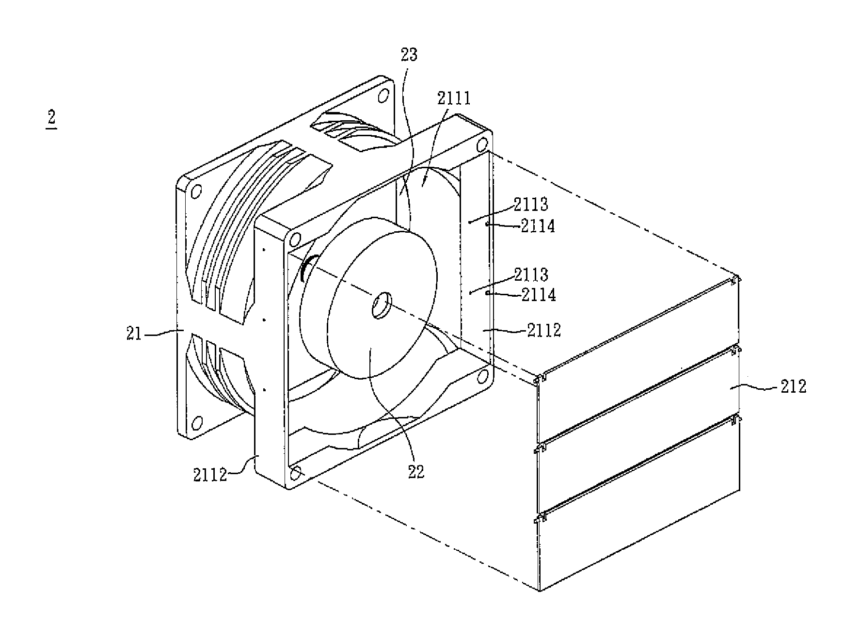
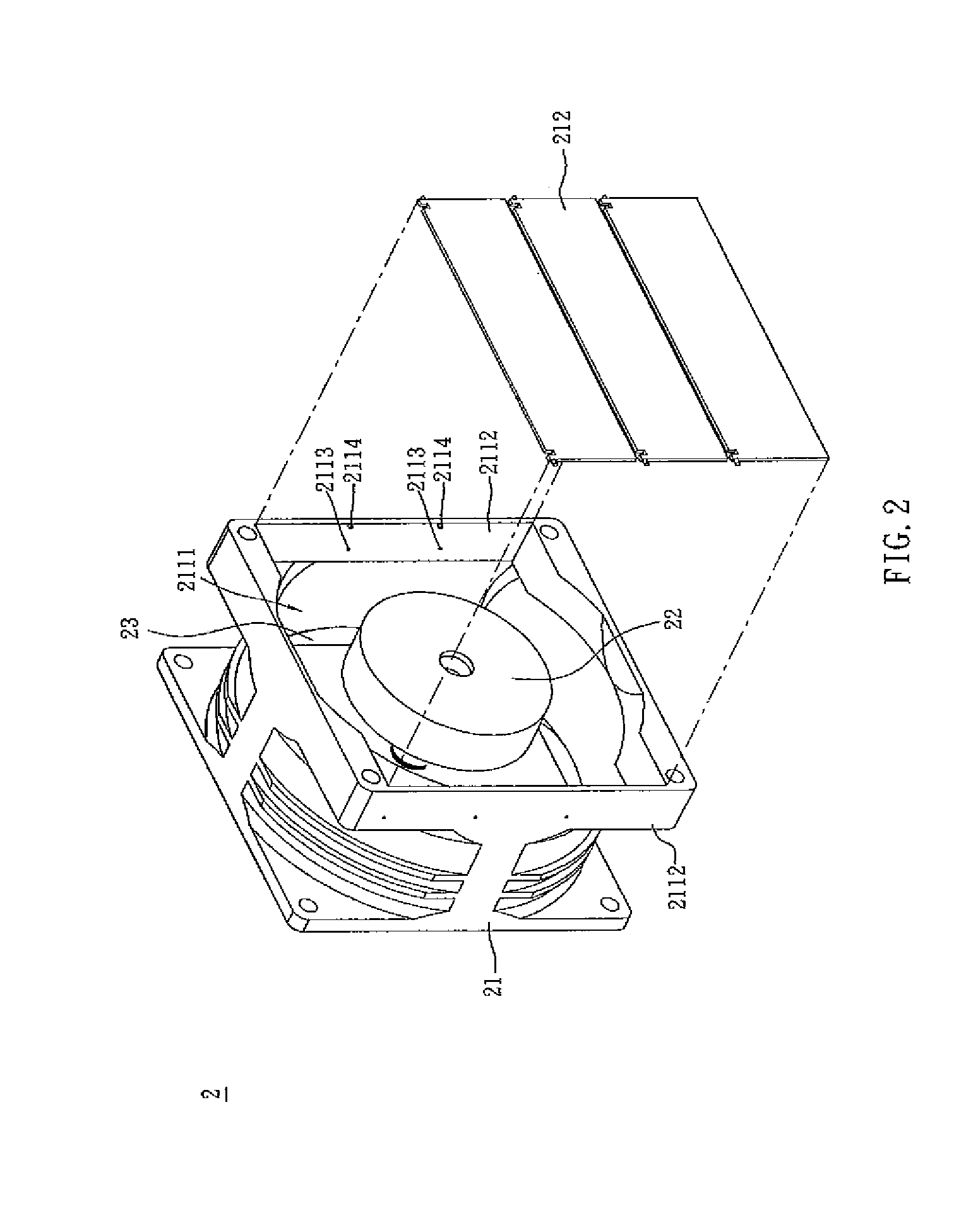
[0023]As shown in FIG. 2, a fan 2 includes a fan housing 21 with an opening 2111 and a motor base 22 connected to the fan housing 21 via guiding vanes 23. The fan housing 21 has two supporting parts 2112 are provided on two opposite sides of the opening 2111 and several fixing parts 2113 symmetrically disposed on the supporting parts 2112. The fan housing 21 further comprises at least one flapper 212 respectively pivoted on the fixing parts 2113 formed on the fan housing 21 for covering an opening 2111 at the outlet side of the fan housing 21.
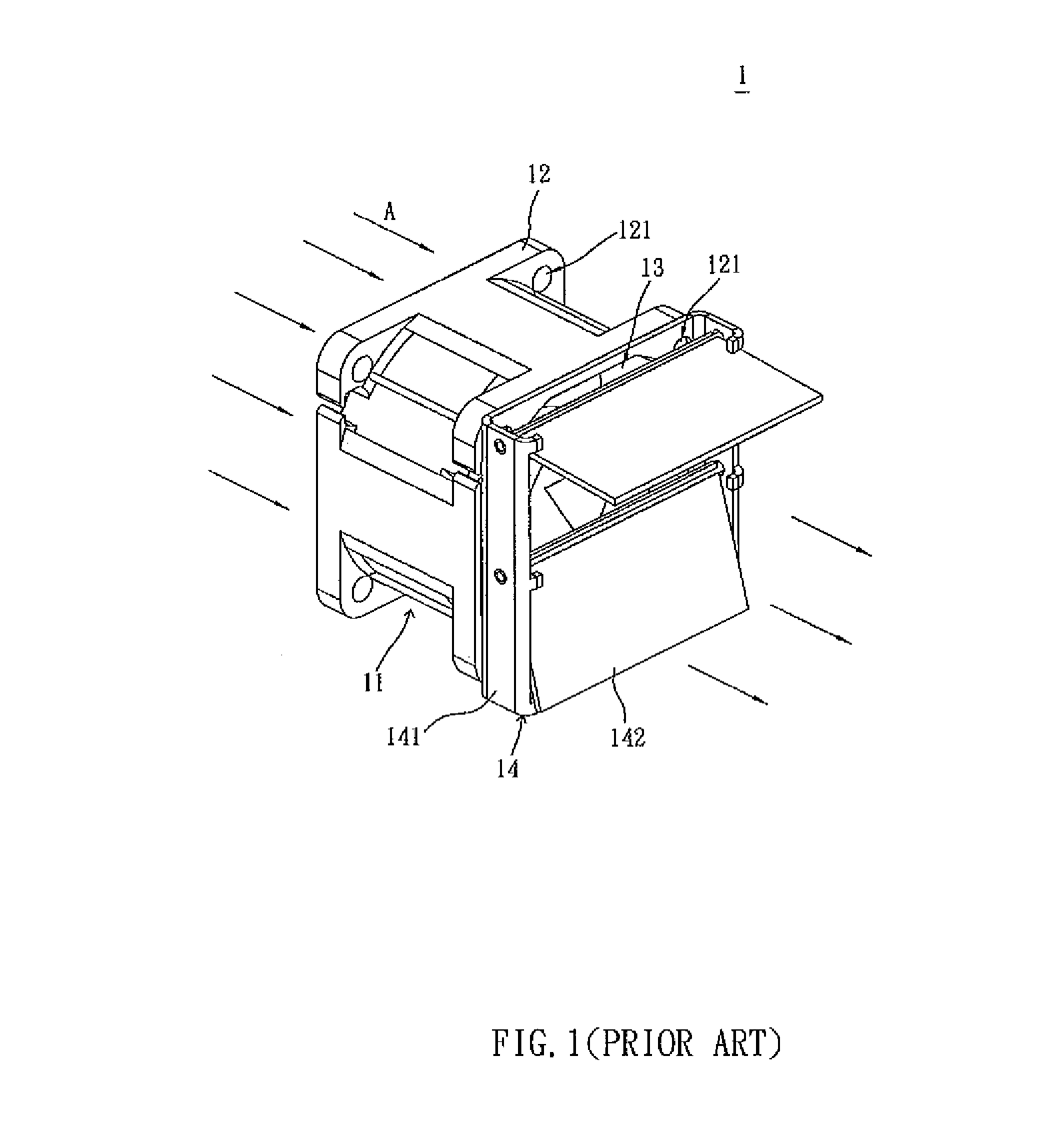
[0024]As shown in FIG. 3, the arrows A show the airflow direction, and the flappers 212 are directly pivotally installed on the fixing parts 2113 to cover the opening 2111. When the airflow passes through the opening 2111, the flappers 212 rotate...
PUM
 Abstract
Description
Claims
Application Information