Methods, apparatus, and article for force feedback based on tension control and tracking through cables

a technology of tension control and force feedback, applied in the field of haptic systems employing force feedback, can solve the problems of inconvenient use for persons wanting or needing to use the conventional haptic interface device, the haptic interface device can be large, and the motor pushes back harder, etc., to achieve the effect of improving the legibility of drawing

Active Publication Date: 2008-06-26
MIMIC TECH
View PDF24 Cites 35 Cited by
  • Summary
  • Abstract
  • Description
  • Claims
  • Application Information

AI Technical Summary

Problems solved by technology

The farther the user penetrates the wall, the harder the motors push back to force the joystick back to the wall surface.
Normally, conventional haptic interface devices can be large and for all practical purposes non-portable.
This means that persons wanting or needing to use a conventional haptic interface device must go to the dedicated room in order to practice on the conventional haptic interface device, which can be very inconvenient to the persons wanting or needing to use the conventional haptic interface device.
A problem with conventional haptic interface devices is that they may be under-utilized due to the inconvenience of the user having to go to the dedicated room.
Another problem is that hospitals and other organizations might not have the resources for housing the conventional haptic interface devices.

Method used


Image

  • Methods, apparatus, and article for force feedback based on tension control and tracking through cables
  • Methods, apparatus, and article for force feedback based on tension control and tracking through cables
  • Methods, apparatus, and article for force feedback based on tension control and tracking through cables

Examples


second embodiment

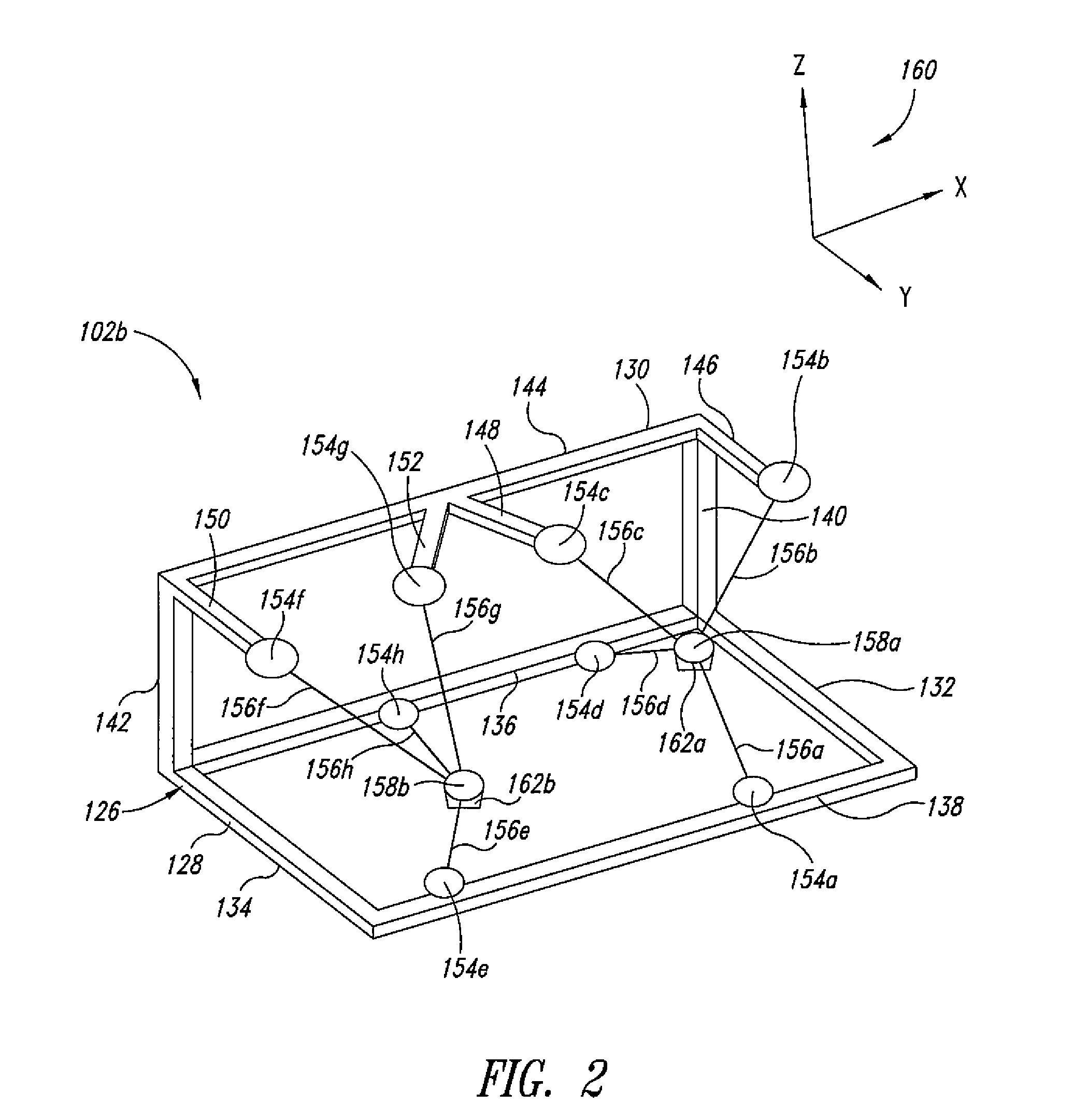
[0041]FIG. 2 shows a workstation 102b according to an illustrated embodiment, with the display omitted for clarity of illustration. The workstation 102b includes a skeletal frame 126 having a base 128 and support system 130. The base 128 includes opposed sides 132, 134 and opposed cross members 136, 138 extending between the sides 132, 134.

[0042]The support system 130 includes a pair of opposed support members 140, 142 extending generally upward from the base 128. A cross member 144 extends between the support members 140, 142. Arms 146, 148, 150, 152 extend outward, generally in the direction of cross member 138, from the cross member 144.

[0043]Translational effecter devices 154b, 154c, 154f, 154g are coupled to the arms 146, 148, 150, 152, respectively. Translational effecter devices 154h, 154d are coupled to the cross member 136, and translational effecter devices 154a, 154e are coupled to the cross member 138.

[0044]The relative locations of the translational effecter devices are...

fourth embodiment

[0099]FIG. 7 shows a workstation 102d according to an illustrated embodiment, with the display omitted for clarity of illustration. In FIG. 7, the various labels having a reference numeral and a prime (′) identify similar components and / or features as those of FIG. 2 that have the same reference numeral without a prime and the various alphanumeric labels (e.g., labels having a reference numeral and a letter of the English alphabet) and a prime (′) identify similar components and / or features as those of FIG. 7 that have the same alphanumeric labels without a prime. The detailed description of such components and / or features are initially provided with respect to the embodiment of FIG. 2 and for the sake of brevity the description of such components and / or features in the context of their subsequently prime-labeled counterparts in FIG. 7 are abbreviated or omitted.

[0100]The workstation 102d includes a first connecting arm 702a that extends between support members 146′ and 148′ and a s...


PUM


Abstract

A haptic interface system includes a cable based haptic interface device and a controller. The controller receives information related to movement of a grip in real-space and generates a stereoscopic output for a display device. The stereoscopic output includes images of a virtual reality tool whose motions mimic motions of the real-space grip.

Description

BACKGROUND OF THE INVENTION[0001]1. Field of the Invention[0002]The disclosure is generally related to haptic systems employing force feedback.[0003]2. Description of the Related Art[0004]Touch, or haptic interaction is a fundamental way in which people perceive and effect change in the world around them. Our very understanding of the physics and geometry of the world begins by touching and physically interacting with objects in our environment. The human hand is a versatile organ that is able to press, grasp, squeeze or stroke objects; it can explore object properties such as surface texture, shape and softness; and it can manipulate tools such as a pen or wrench. Moreover, touch interaction differs fundamentally from all other sensory modalities in that it is intrinsically bilateral. We exchange energy between the physical world and ourselves as we push on it and it pushes back. Our ability to paint, sculpt and play musical instruments, among other things depends on physically per...

Claims


Application Information

Patent Timeline
Patent Type & Authority Applications(United States)
IPC IPC(8): G09G5/00
CPCG06F3/0346G06F3/016
Inventor BERKLEY, JEFFREY J.VOLLENWEIDER, MARCKIM, SEAHAK
Owner MIMIC TECH
Why Eureka
Try Eureka