Apparatus and method for controlling a circuit breaker trip device

Active Publication Date: 2008-06-26
ABB (SCHWEIZ) AG
View PDF19 Cites 21 Cited by
  • Summary
  • Abstract
  • Description
  • Claims
  • Application Information

AI Technical Summary

Benefits of technology

[0021]In one aspect of the present invention, an apparatus and method for controlling the operation of a circuit breaker trip solenoid includes a control circuit configured to receive a trip activation signal in response to a predetermined condition. The control circuit, in response to said activ

Problems solved by technology

The line and neutral conductors are passed through the coil such that when a line to ground fault exists, it creates an imbalance between the two currents in the two conductors which is level detected.
Arcing faults are intermittent high impedance faults caused for instance by worn insulation, loose connections, broken conductors, and the like.
Because of their intermittent and high impedance nature, arcing faults do not always generate currents of sufficient instantaneous magnitude or sufficient average current to trigger the conventional overcurrent trip units.
In some cases, when conventional circuit breakers employ an electromechanical solenoid to trigger the tripping mechanism, the energizing signal to the electromechanical solenoid c

Method used


Image

  • Apparatus and method for controlling a circuit breaker trip device
  • Apparatus and method for controlling a circuit breaker trip device
  • Apparatus and method for controlling a circuit breaker trip device

Examples


Embodiment Construction

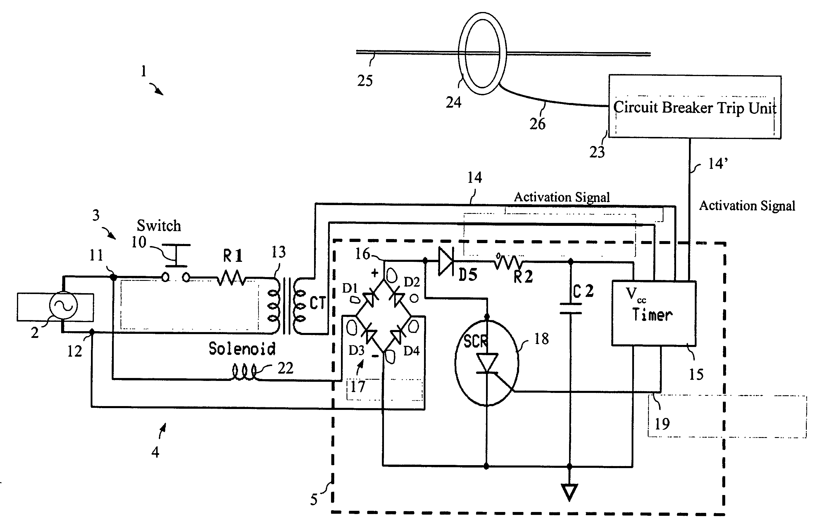
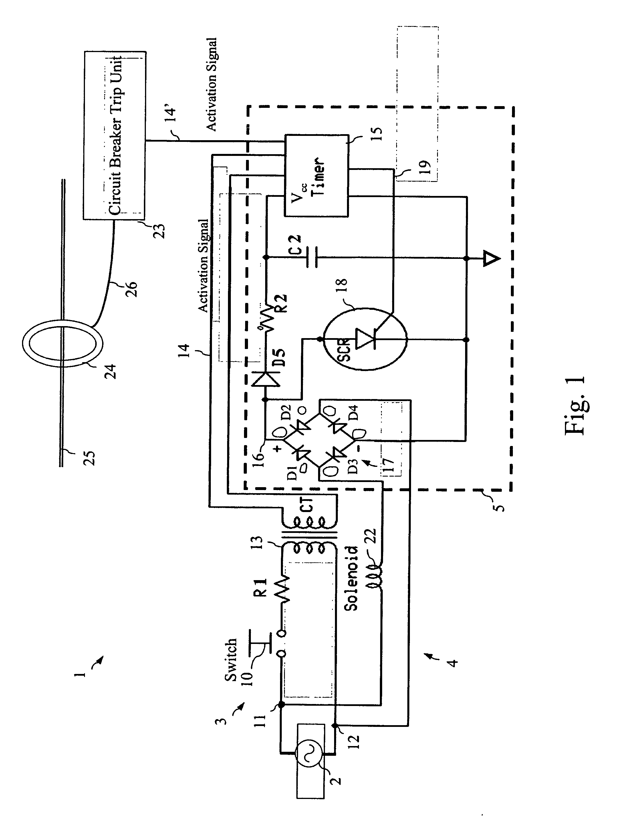
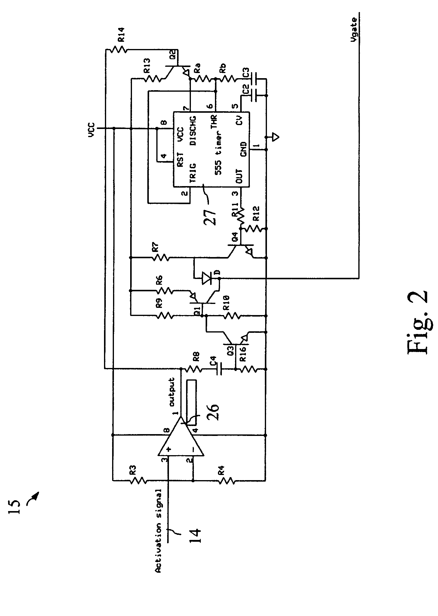
[0033]A schematic of the apparatus for controlling the operation of a circuit breaker trip solenoid in accordance with the present invention is generally illustrated in FIG. 1, FIG. 2, and FIG. 3. As these embodiments of the present invention are described, reference should also be made to FIG. 7 as necessary, as a depiction of various waveforms associated with the described apparatus is provided.

[0034]Referring initially to FIG. 1, an exemplary solenoid control system 1 is depicted. As shown, an external AC source 2 provides power to an activation signal control path 3 and a solenoid circuit path 4. Both the activation signal control path 3 and the solenoid circuit path 4 are in signal communication with a solenoid control unit 5. As is further depicted, the solenoid control unit 5 includes a full wave bridge rectifier 17, a filtering diode D5, a current limiting resistor R2, a smoothing capacitor C2, a timer 15, and a silicon controlled rectifier (SCR) or other suitable solid stat...


PUM


Abstract

An apparatus and method for controlling the operation of a solenoid in a circuit breaker includes a control circuit configured to receive an activation signal in response to a predetermined condition. The control circuit, in response to said activation signal, provides a first energizing signal to the solenoid for a first predetermined period, and cuts off the first energizing signal for a second predetermined period. The control circuit further provides a second energizing signal to the solenoid for a third predetermined period.

Description

CROSS REFERENCE TO RELATED APPLICATIONS[0001]This application is a continuation-in-part application of U.S. application Ser. No. 11 / 614,457, filed Dec. 21, 2006, the contents of which are incorporated herein by reference in their entirety.BACKGROUND OF THE INVENTION[0002]The present invention relates generally to circuit breaker trip systems, and more specifically to an apparatus and method for changing the operative condition of a circuit breaker.DESCRIPTION OF THE PRIOR ART[0003]Circuit Breakers, and more specifically molded case and air circuit breakers, are well known in the prior art. In general, the function of a circuit breaker is to electrically engage and disengage a selected circuit from an electrical power supply. Circuit breakers are intended to provide protection in electrical circuits and distribution systems against a variety of electrical faults, for example, electrical overload conditions, short-circuit fault currents, as well as ground fault and arcing fault condit...

Claims


Application Information

Patent Timeline
IPC IPC(8): H01H71/74
CPCH01H47/32H01H71/24H01H71/121
Inventor DWYER, SEANMASON, HENRY HALLRIVERS, CECILSHAIKH, SOHAIB UDDINWILLIAMS, CRAIG B.
Owner ABB (SCHWEIZ) AG
Why Eureka
Try Eureka