Image forming device to determine paper width and image forming method thereof

a technology of image forming and forming roller, which is applied in the direction of electrographic process equipment, instruments, optics, etc., can solve the problems of component damage, deformation of printing quality, and roller surface damage under a large amount of heat, so as to prevent component damage and degradation of printing quality

Inactive Publication Date: 2008-06-26
S PRINTING SOLUTION CO LTD
View PDF3 Cites 2 Cited by
  • Summary
  • Abstract
  • Description
  • Claims
  • Application Information

AI Technical Summary

Benefits of technology

[0011]The present general inventive concept provides an image forming device which can sense a paper width using an existing sensor without an additional structure and prevents component damage and printing quality degradation by applying a printing condition according to the sensing result.

Problems solved by technology

In this case, the size difference between the actual printing paper size and the default A4 printing paper size may cause damage to the components.
As a result, the roller surface under a great amount of heat may be damaged due to temperature changes.
Consequently, the printing quality may be degraded.
However, these conventional image forming devices cannot apply proper printing conditions with respect to printing papers having non-standard printing paper sizes.
As discussed above, component damage may result.
Additionally, when a paper width sensor is provided to sense the paper width, additional cost associated with the addition thereof is inevitable.

Method used


Image

  • Image forming device to determine paper width and image forming method thereof
  • Image forming device to determine paper width and image forming method thereof
  • Image forming device to determine paper width and image forming method thereof

Examples


Embodiment Construction

[0031]Reference will now be made in detail to embodiments of the present general inventive concept, examples of which are illustrated in the accompanying drawings, wherein like reference numerals refer to the like elements throughout. The embodiments are described below to explain the present general inventive concept by referring to the figures.

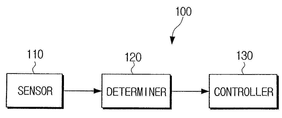
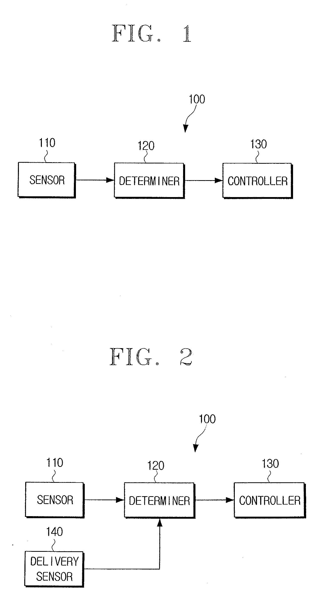
[0032]FIG. 1 is a block diagram illustrating an image forming device according to an embodiment of the present general inventive concept. The image forming device 100 includes a sensor 110, a determiner 120, and a controller 130. The image forming device 100 can be a printer, a copier, a fax machine, or a multifunction processor.

[0033]The sensor 110 is disposed at a predetermined location of the image forming device 100 from which papers 10 are discharged, so that the discharged papers may touch the sensor 110. Accordingly, the sensor 110 outputs a sensing signal in response to the papers 10 being discharged from a location of the image form...


PUM


Abstract

An image forming device includes a sensor to detect whether a paper is discharged or not, a determiner to determine a paper width according to whether a sensing signal is output from the sensor when a printing job is executed, and a controller to control a subsequent printing operation according to the determination result of the determiner. After the printing job is initiated, the determiner determines a normal width when the sensing signal is output within a preset time, and the determiner determines a narrow width when the sensing signal is not output within the present time. Accordingly, using an existing sensor, the paper width can be detected and the appropriate printing process can be performed.

Description

CROSS-REFERENCE TO RELATED APPLICATIONS[0001]This application claims the benefit under 35 U.S.C. § 119 (a) from Korean Patent Application No. 2006-133109 filed on Dec. 22, 2006, in the Korean Intellectual Property Office, the disclosure of which is incorporated herein in its entirety.BACKGROUND OF THE INVENTION[0002]1. Field of the Invention[0003]The present general inventive concept relates generally to an image forming device and an image forming method thereof. More particularly, the present general inventive concept relates to an image forming device to detect a width of a paper using a sensor to detect whether the paper is discharged and to control a subsequent printing operation according to the detection result, and an image forming method thereof.[0004]2. Description of the Related Art[0005]With the advancement of electronic technology, a variety of computer peripheral devices have been developed. Representative peripheral devices include image forming devices such as printe...

Claims


Application Information

Patent Timeline
Patent Type & Authority Applications(United States)
IPC IPC(8): G03G15/00
CPCG03G15/5029G03G15/6552G03G2215/00734G03G2215/00421G03G2215/00329G03G15/00
Inventor LEE, UI-CHOON
Owner S PRINTING SOLUTION CO LTD
Why Eureka
Try Eureka