Control apparatus for vehicular drive system

Inactive Publication Date: 2008-06-26
TOYOTA JIDOSHA KK
View PDF16 Cites 20 Cited by
  • Summary
  • Abstract
  • Description
  • Claims
  • Application Information

AI Technical Summary

Benefits of technology

[0007]The present invention was made in view of the background art described above. It is therefore an object of this invention to provide a control apparatus for a vehicular drive system having a power transmitting d

Problems solved by technology

During this shifting action of the power transmitting device, the shift-down and shift-up actions of the first and second transmission portions would cause the engine speed to change in the opposite directions, in the absence of the step-variable shifting control portion of the present control apparatus, so that the shift-down and shift-up actio

Method used


Image

  • Control apparatus for vehicular drive system
  • Control apparatus for vehicular drive system
  • Control apparatus for vehicular drive system

Examples


Example

Embodiment 1

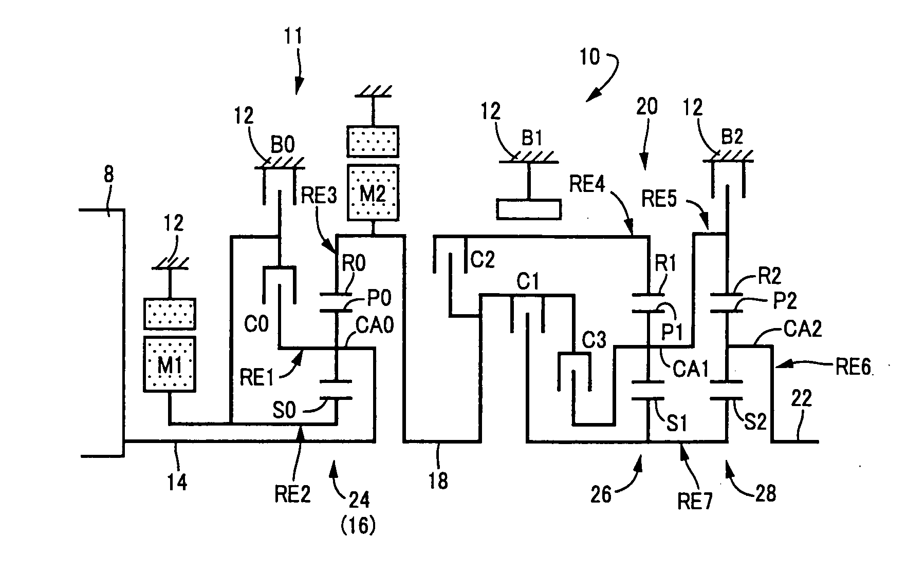
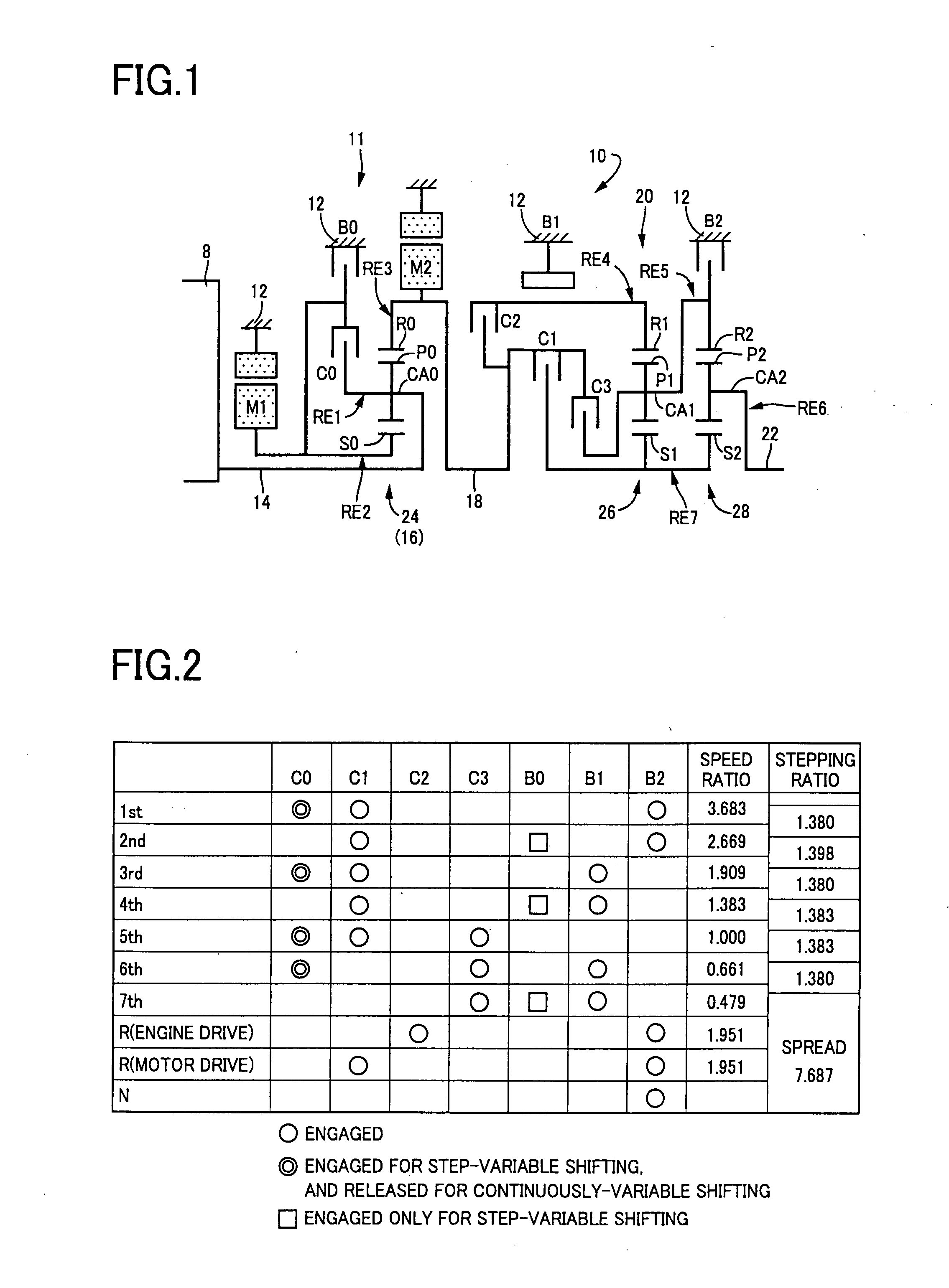
[0060]Referring first to the schematic view of FIG. 1, there is shown a transmission mechanism (power transmitting device) 10 constituting a part of a drive system for a hybrid vehicle, which drive system is controlled by a control apparatus according to a first embodiment of this invention. As shown in FIG. 1, the transmission mechanism 10 includes: an input rotary member in the form of an input shaft 14 connected directly or indirectly via a pulsation absorbing damper or vibration damping device (not shown) to an engine 8; a first transmission portion or a continuously-variable transmission portion in the form of a differential portion 11 connected to the input shaft 14; a second transmission portion or step-variable or multiple-step transmission portion in the form of an automatic transmission portion 20 disposed in a power transmitting path between the differential portion 11 and drive wheels 38 of the vehicle, and connected in series via a power transmitting member ...

Example

Second Embodiment

[0125]The electronic control device 40 provided according to a second embodiment of this invention is provided with a step-variable shifting control portion 73 which includes concurrent switching / shifting determining means 74, step-variable-transmission-portion control means 75, continuously-variable-transmission-portion control means 76 and switching completion determining means 78. The concurrent switching / shifting determining means 74 is configured to determine whether a switching action of the differential portion 11 between the continuously-variable and step-variable shifting state and a shifting action of the automatic transmission portion 20 should take place or occur concurrently. This determination is made on the basis of the vehicle condition represented by the vehicle speed V and the required output torque Tour, and according to the switching boundary line map and the shifting boundary line map indicated in FIG. 6 by way of example.

[0126]When the vehicle ...

Example

Third Embodiment

[0143]FIG. 14 is a schematic view showing an arrangement of a transmission mechanism 90 which is controllable by the electronic control device of the first embodiment of FIG. 5 or second embodiment of FIG. 10 according to a third embodiment of this invention, and FIG. 15 is a table indicating shifting actions of the transmission mechanism 90 placed in the step-variable shifting state, in relation to different combinations of the operating states of hydraulically operated frictional coupling devices to effect the respective shifting actions, while FIG. 16 is a collinear chart indicating relative rotating speeds of the transmission mechanism 90 placed in the step-variable shifting state, in different gear positions of the transmission mechanism 90.

[0144]The transmission mechanism 90 is arranged to be accommodated in a transaxle casing 91 of on an FF vehicle (front-engine front-drive vehicle), such that the differential portion 11 including the first electric motor M1, ...


PUM


Abstract

A control apparatus for a vehicular drive system including a first or continuously-variable transmission portion and a second or step-variable transmission portion which are disposed in series with each other, the first transmission portion being switchable between a continuously-variable shifting state and a step-variable shifting state, and the second transmission portion having a plurality of gear positions having respective speed ratios, the control apparatus including a step-variable shifting control portion configured to be operable upon concurrent occurrences of a shift-down action of one of the first and second transmission portions and a shift-up action of the other of the first and second transmission portions, to control the first transmission portion placed in the step-variable shifting state such that the shifting action of the first transmission portion is performed in synchronization with the shifting action of the second transmission portion, or operable upon concurrent occurrences of a switching action of the first transmission portion between the two shifting sates and a shifting action of the second transmission portion, to control the first transmission portion such that the switching action is performed during the shifting action of the second transmission portion.

Description

[0001]The present application claims the benefits of Japanese Patent Application Nos. 2006-297175 and 2006-297176 both filed Oct. 31, 2006, the disclosure of which is herein incorporated by reference in its entirety.BACKGROUND OF THE INVENTION[0002]1. Field of the Invention[0003]The present invention relates in general to a control apparatus for a vehicular drive system including a first transmission portion (continuously-variable transmission portion) and a second transmission portion (step-variable transmission portion) disposed in series with each other, the first transmission portion being operable selectively as an electrically controlled continuously-variable transmission and a step-variable transmission, while the second transmission portion having a plurality of gear positions having respective speed ratios which change in steps. The continuously-variable transmission portion (first transmission portion) is switchable between a continuously-variable shifting state in which i...

Claims


Application Information

Patent Timeline
IPC IPC(8): B60W10/10
CPCB60K6/365Y10T477/619B60K6/547B60W20/00F16H3/728F16H61/0437F16H61/08F16H61/686F16H61/702F16H2037/0873F16H2061/085F16H2200/0056F16H2200/201F16H2200/2048Y02T10/6239B60K6/445Y02T10/62B60W10/06B60W10/10B60W20/30
Inventor TABATA, ATSUSHIMATSUBARA, TOORUSHIBATA, HIROYUKIKUMAZAKI, KENTA
Owner TOYOTA JIDOSHA KK
Why Eureka
Try Eureka