Seal retainer device and power transmission unit with seal retainer device

a technology of sealing retainer and power transmission unit, which is applied in the direction of engine seals, gearing, yielding couplings, etc., can solve problems such as complicated design, and achieve the effect of reducing the cost of engineering design and production technology with regard to support surfaces, and avoiding the possibility of costly and laborious

Inactive Publication Date: 2008-07-03
SCHAEFFLER TECH AG & CO KG
View PDF13 Cites 10 Cited by
  • Summary
  • Abstract
  • Description
  • Claims
  • Application Information

AI Technical Summary

Benefits of technology

[0004]The object of the invention is therefore to further develop a power transmission unit of the type named at the beginning in such a manner that its position can be fixed by sealing devices, in particular by a plurality of sealing devices situated in various positions on an element, with the least possible expense and effort. Furthermore, the cost of engineering design and production technology with regard to the support surfaces for the sealing devices is to be kept as low as possible; that is, if possible no modifications of individual parts should be necessary with regard to specific types of sealing devices.
[0013]According to the second option, the seal retainer device has at least one second functional surface oriented in the axial direction, which forms an axial or radial sliding bearing surface between the hub and a sub-area of the housing that forms an inner circumference. This second functional surface can also be formed by a plurality of partial surface areas. In the simplest case, with cap-like design, the end face which is already present anyway on the connecting piece is used. In order to prevent blocking of the pressure chamber in this case, beads, projections or recesses are provided either on the internal periphery of the housing, oriented in the axial direction to the hub, or on the end face of the hub directed toward the internal periphery of the housing in the axial direction, to realize a port for the flow of process fluid.

Problems solved by technology

Depending on the design of the power transmission unit, in particular the arrangement of the individual elements with respect to each other and the design of the individual pressure chambers and their connections with each other, this creates a very complicated design with regard to the grooves provided for the individual sealing devices, these grooves being matched to the sealing devices that are to be used.

Method used


Image

  • Seal retainer device and power transmission unit with seal retainer device
  • Seal retainer device and power transmission unit with seal retainer device
  • Seal retainer device and power transmission unit with seal retainer device

Examples


Embodiment Construction

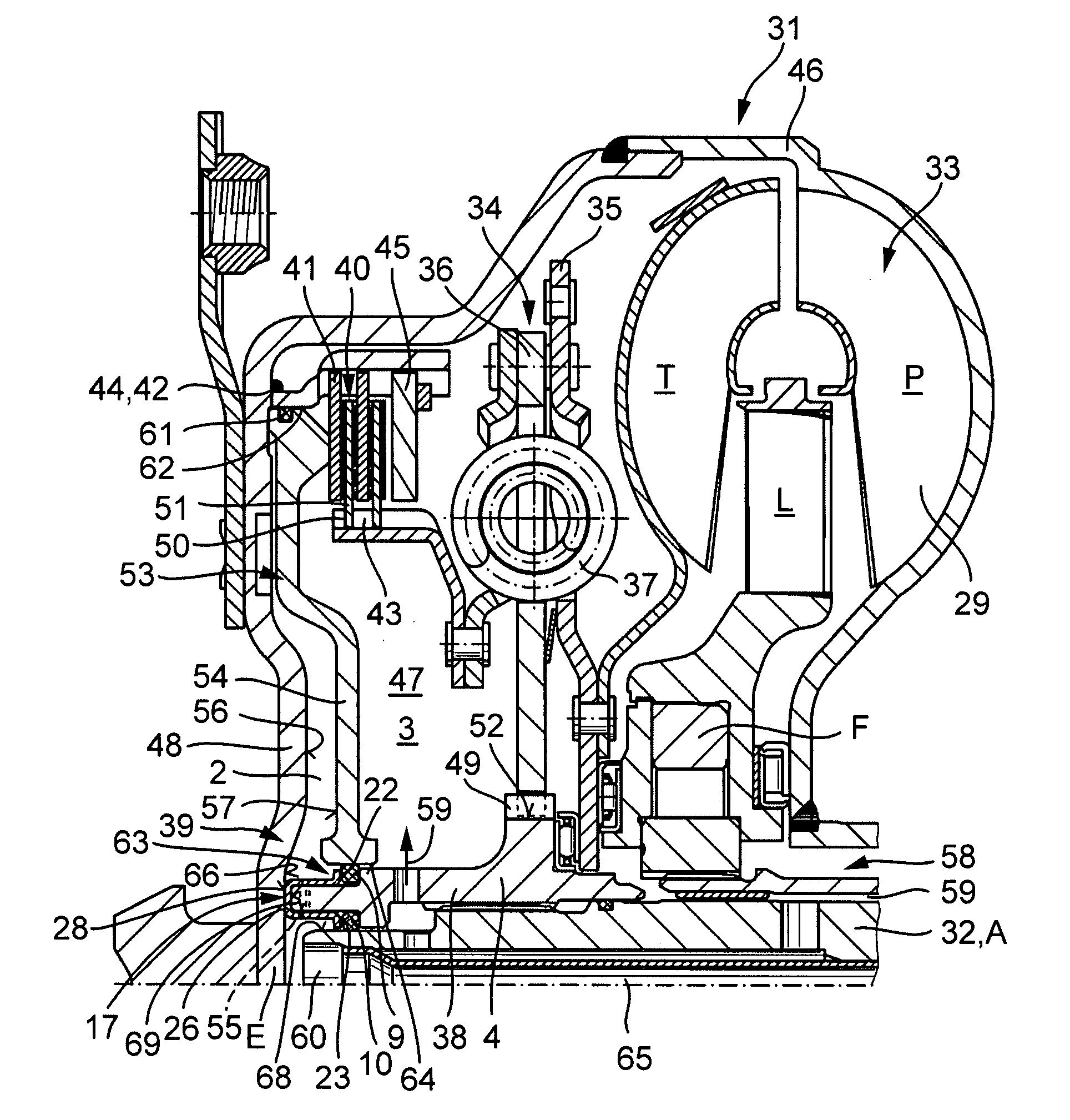
[0026]FIG. 1 explains by way of example in an axial section one possible embodiment of seal retainer device 1 according to the invention for fixing the location of at least one, preferably of a plurality of sealing devices for delimiting two pressure chambers in a power transmission unit between two components. This can be of various design in terms of the geometric form, but includes at least one, in the depicted case two contact surfaces 22, 23 formed on flange-type projections 20 and 21 oriented in a radial direction, for fixing the position of one sealing device each in radial and / or axial direction, at least one first functional surface, here in exemplary fashion first inner and outer functional surfaces 71, 70 for linking or attachment to a component, and preferably in addition second functional surface 28, for example for forming an axial or radial bearing sliding surface. In the depicted case the seal retainer device 1 is designed as ring-shaped cap-like element 17 with C-sh...


PUM


Abstract

A seal retainer device for fixing the position of at least one sealing device, comprising at least one contact surface for fixing the position of a seal in the radial and / or axial direction, a first functional surface for linking to a component, and at least one second functional surface to form an axial or radial bearing sliding surface. In addition, the invention relates to a power transmission unit having a seal retainer that holds seals for sealing off two pressure chambers.

Description

CROSS REFERENCE TO RELATED APPLICATIONS[0001]This patent claims priority of German Patent Application No. 10 2006 061 551.4, filed Dec. 27, 2006, which application is incorporated herein by reference.FIELD OF THE INVENTION[0002]The invention relates generally to a seal retainer device, and, more particularly, to a seal retainer device and power transmission unit with a seal retainer device.BACKGROUND OF THE INVENTION[0003]In power transmission units for transferring power between a drive engine and a transmission, comprising a hydrodynamic component and an engageable and disengageable clutch device which serves to bypass the transferring of power via the hydrodynamic component, normally different pressure chambers are provided. Two pressure chambers with corresponding connections are provided in the hydrodynamic component only for conveying process fluids, whereby it is also being to control the conveying of process fluids possible via the connections. A first pressure chamber is fo...

Claims


Application Information

Patent Timeline
Patent Type & Authority Applications(United States)
IPC IPC(8): F16J15/16F16H57/00
CPCF16H45/02F16H2045/021Y10T74/19633F16H2045/0284F16J15/062F16H2045/0247
Inventor DEGLER, MARIO
Owner SCHAEFFLER TECH AG & CO KG
Why Eureka
Try Eureka