Device for securing a tension element against unintentional release

a technology of unintentional release and clamping element, which is applied in the direction of threaded fasteners, bearing unit rigid supports, screws, etc., can solve the problems of corresponding loss of pre-tensioning and total failure of respective transmissions, and achieve the effect of avoiding the possibility of expens

Active Publication Date: 2019-06-25
ZF FRIEDRICHSHAFEN AG
View PDF15 Cites 0 Cited by
  • Summary
  • Abstract
  • Description
  • Claims
  • Application Information

AI Technical Summary

Benefits of technology

[0004]Exemplary aspects of the present invention assist with providing a device that can be mounted on a radially inner component in a manner that is as free of backlash as possible, but thereby carrying into effect a mounting with the least possible expense.

Problems solved by technology

However, micro-movements in the form of minor twists of the internal ring that is located directly adjacent and serves as the head contact surface of the clamping nut may lead to the unintended release of the clamping nut, which may then result in a corresponding loss of the pre-tensioning and possibly even a total failure of the respective transmission.

Method used


Image

  • Device for securing a tension element against unintentional release
  • Device for securing a tension element against unintentional release
  • Device for securing a tension element against unintentional release

Examples


Embodiment Construction

[0035]Reference will now be made to embodiments of the invention, one or more examples of which are shown in the drawings. Each embodiment is provided by way of explanation of the invention, and not as a limitation of the invention. For example, features illustrated or described as part of one embodiment can be combined with another embodiment to yield still another embodiment. It is intended that the present invention include these and other modifications and variations to the embodiments described herein.

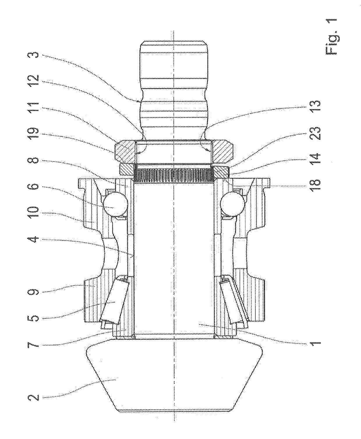
[0036]FIG. 1 shows a first application example of the invention. FIG. 1 shows a sectional view of a bearing assembly of a shaft 1 formed as a bevel pinion shaft. In this case, this bevel pinion shaft may be used, for example, for connecting an output side of an automatic transmission with an axle differential on the drive side of the automatic transmission. The shaft 1 is equipped at a front end with a bevel pinion 2, across which, in the installed state, a tooth engagement with a...


PUM


Abstract

A device for securing a clamping element against unintentional release includes a disk-shaped structure penetrated in an axial manner by a bore hole. A driving profile is defined by the bore hole. The disk-shaped structure is positionable on a component such that the bore hole engages a profile on the component to establish a torque-proof coupling of the disk-shaped structure and the component. The disk-shaped structure has a pair of contact surfaces. Each contact surface of the pair of contact surfaces runs radially and is positioned at a respective axial side of the disk-shaped structure. A profile plane of the driving profile is tilted at an angle with respect to a radial plane of each contact surface of the pair of contact surfaces. A related mounting arrangement is also provided.

Description

FIELD OF THE INVENTION[0001]The invention relates generally to a device for securing a clamping element against unintentional release, with a disk-shaped structure that is penetrated in an axial manner by a bore hole, whereas the structure is provided for an inner diameter with a driving profile defined by the bore hole, which, in the placement of the structure, engages with the bore hole on a radially inner component in a profile provided on the part of such component and thereby establishes a torque-proof coupling of the structure with this component, and whereas the structure is provided, in an axial manner on both sides, with contact surfaces that run in a radial manner. Furthermore, the invention relates generally to a mounting arrangement with which the aforementioned device is applied.BACKGROUND[0002]In the field of transmissions, roller bearings are sometimes mounted with the assistance of clamping nuts, which attain a sufficient axial pre-tensioning of the successive roller...

Claims


Application Information

Patent Timeline
Patent Type & Authority Patents(United States)
IPC IPC(8): F16B39/24F16C25/06F16C35/06F16C35/063F16H61/36F16D1/108F16C19/06F16C19/49F16D1/10
CPCF16B39/24F16C25/06F16C35/061F16C35/063F16D1/108F16H61/36F16D2001/103F16C19/06F16C19/497F16C2226/80F16C2361/61F16B21/10F16C35/12F16D1/00
Inventor LIST, MATTHIASDECKER, INGOSELBHERR, SIEGFRIED
Owner ZF FRIEDRICHSHAFEN AG
Why Eureka
Try Eureka