
Electrically Controlled Valve

Inactive Publication Date: 2008-08-28
CONTINENTAL TEVES AG & CO OHG
View PDF8 Cites 9 Cited by
  • Summary
  • Abstract
  • Description
  • Claims
  • Application Information

AI Technical Summary

Benefits of technology

[0007]An object of the invention involves designing a valve of the indicated type with minimum possible effort in such a fashion that the valve slide provides a permanently high control dynamics irrespective of its moving direction, while using simple, functionally reliable means and while avoiding the above-mentioned drawbacks.

Problems solved by technology

This arrangement equally increases the cost and complexity of construction and, in connection with the moving coil at the valve slide, increases the mass as well as consequently the system's inertia.

Method used


Image

  • Electrically Controlled Valve
  • Electrically Controlled Valve

Examples


Embodiment Construction

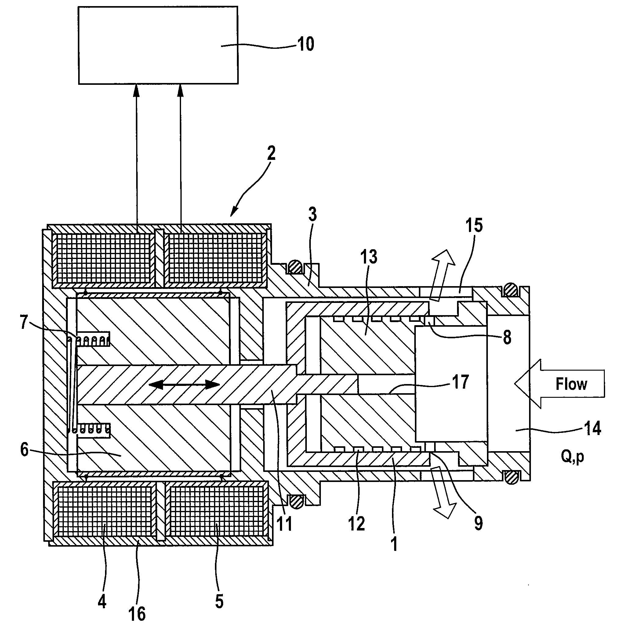
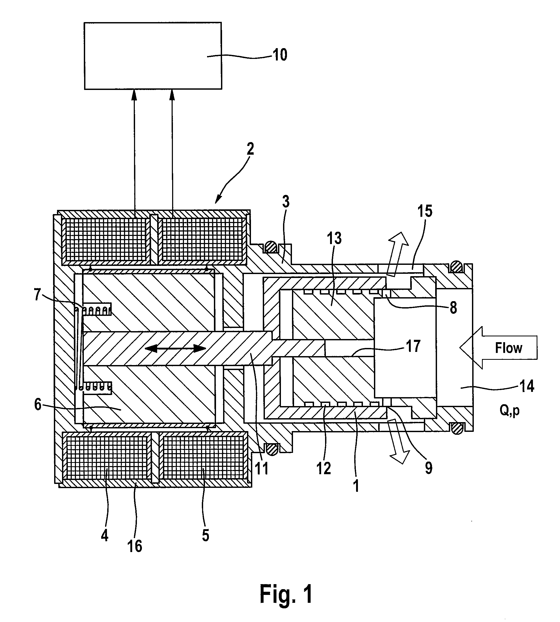
[0011]For actuation of a valve slide 1 that is guided in a housing 3, the valve includes a magnetic drive 2, which actuates the valve slide 1 in the housing 3 for the variable volume flow control between a valve inlet 14 and a valve outlet 15 in such a manner that a passage 8 arranged in the housing 3 is invariably opened or closed by a control edge 9 of the valve slide 1.

[0012]Therefore, the invention arranges that the moving direction of the valve slide 1 can be reversed depending on the electric energization of the magnetic drive 2, to what end the valve slide 1 can be driven by a magnetic drive 2 provided as a reversible lifting magnet.

[0013]For this purpose, the magnetic drive 2 includes a first and a second magnet coil 4, 5 being fixed at the housing 3, the said coils being electrically actuatable into the one or the other direction jointly or irrespective of one another for the optional actuation of the armature 6 that is connected to the valve slide 1. The two magnet coils 4...


PUM


Abstract

An electrically controlled valve, in particular for the variable adjustment of the damper characteristic curve of a vibration damper, comprising a magnetic drive for actuating a valve slide that is guided in a housing in one moving direction, as well as a passage arranged in the housing between a valve inlet and a valve outlet for the variable volume flow control, the passage cooperating with a control edge of the valve slide. The moving direction of the valve slide is electrically reversible, thereby resulting in a comparatively simple mechanical layout for the valve for variably controlling the characteristic curve of the valve.

Description

[0001]This application is the U.S. national phase application of PCT International Application No. PCT / EP2006 / 064072, filed Jul. 11, 2006, which claims priority to German Patent Application No. DE102005033877.1, filed Jul. 20, 2005 and German Patent Application No. DE102006007157.3, filed Feb. 16, 2006, the contents of such applications being incorporated by reference herein.BACKGROUND OF THE INVENTION[0002]1. Field of the Invention[0003]The present invention relates to an electrically controlled valve, in particular for use in a shock absorber.[0004]2. Description of the Related Art[0005]EP 0 627 052 B1 discloses a valve of the generic type, the valve slide of which carries a moving coil whose current supply is executed by way of a bending spring defining the basic positioning of the valve slide in the housing. The housing carries a permanent magnet cooperating with the moving coil so that comparatively great effort and structure is needed in total for the electromechanical actuati...

Claims


Application Information

Patent Timeline
IPC IPC(8): F16K31/06F16F9/00F16F7/00
CPCF16K31/0679F16F9/466
Inventor FEIGEL, HANS-JORGHOFFMAN, JAN
Owner CONTINENTAL TEVES AG & CO OHG
Learn More