
Motor Vehicle Having a Hybrid Drive, and Method for Operating a Hybrid Drive

a hybrid drive and motor vehicle technology, applied in the direction of gas pressure propulsion mounting, propulsion parts, transportation and packaging, etc., can solve the problem of only being able to represent the drive-away behavior of a conventional motor vehicle in torque-controlled operation of an electro machine, and achieve the effect of high control performance and rise in the rotational speed of the electro machin

Active Publication Date: 2010-01-07
ROBERT BOSCH GMBH
View PDF10 Cites 9 Cited by
  • Summary
  • Abstract
  • Description
  • Claims
  • Application Information

AI Technical Summary

Benefits of technology

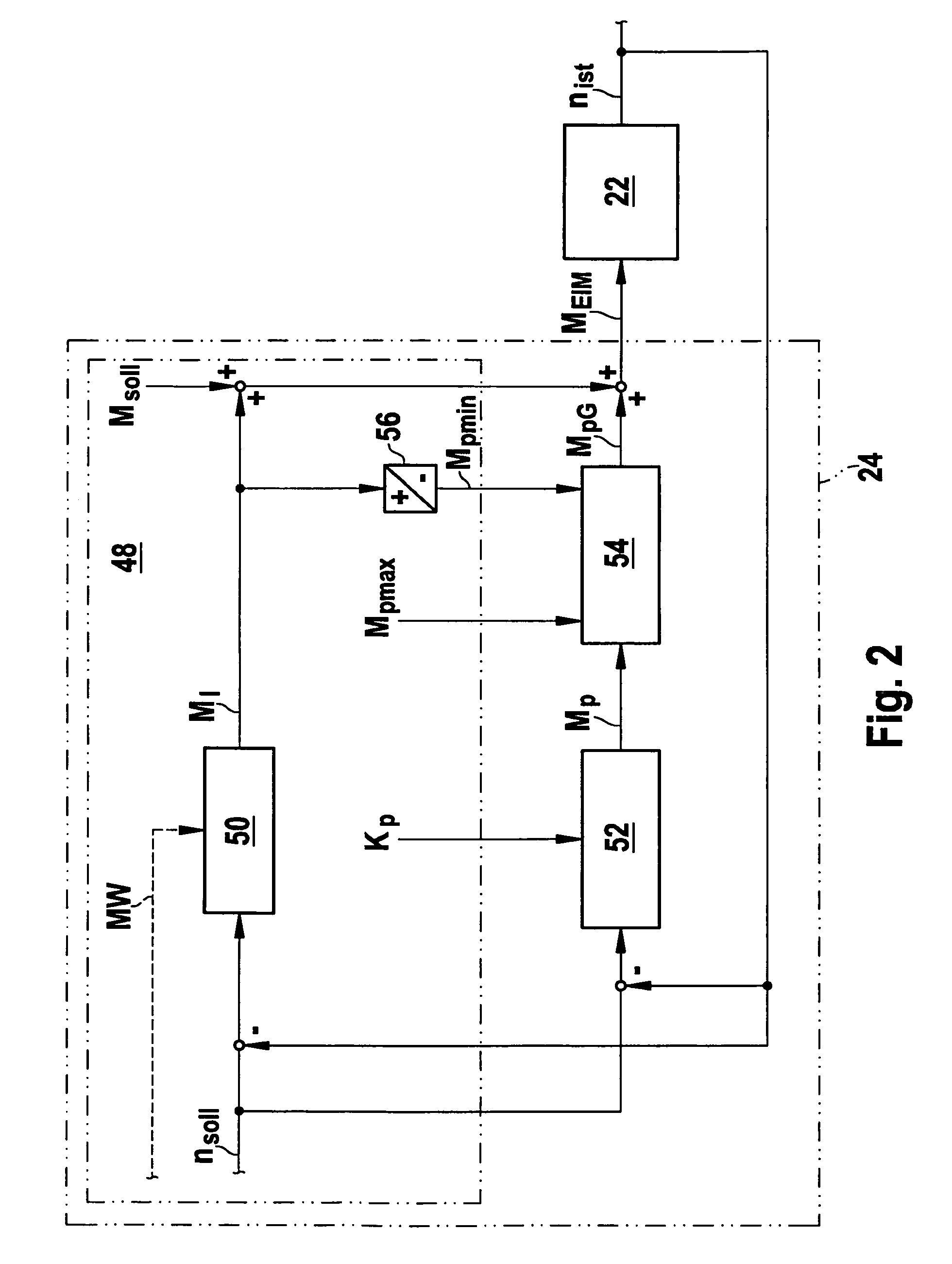
[0006]In one advantageous method step, the closed-loop speed control is divided into a fast component, e.g., a proportional component, and a slow component, e.g., an integral-action component, the proportional component being calculated in the control unit of the electro machine, and the integral-action component being calculated in a control unit in which a torque path is calculated, and / or in which torque requests, e.g., from the driving pedal or the vehicle speed controller, are read in and / or calculated. Most of the signals required for the transition from rpm-regulated to torque-controlled operation are available there. The calculation of the integral-action component may be implemented in the engine control unit. Since the proportional component is calculated in the control unit of the electro machine, a limitation of the effect of the controller by signal propagation delays between different control units is able to be reduced. High control performance or high dynamics of the control is achievable.
[0015]In one advantageous development, the proportional component is integrated in the control unit of the electro machine. This hardware partitioning (which may be used) results in a small interface width between the control units, and in high control performance or high dynamics of the control.

Problems solved by technology

With an automatic transmission and an open mechanical lockup clutch, the drive-away behavior of a conventional motor vehicle in a torque-controlled operation of the electro machine is representable only inadequately.

Method used


Image

  • Motor Vehicle Having a Hybrid Drive, and Method for Operating a Hybrid Drive
  • Motor Vehicle Having a Hybrid Drive, and Method for Operating a Hybrid Drive
  • Motor Vehicle Having a Hybrid Drive, and Method for Operating a Hybrid Drive

Examples


Embodiment Construction

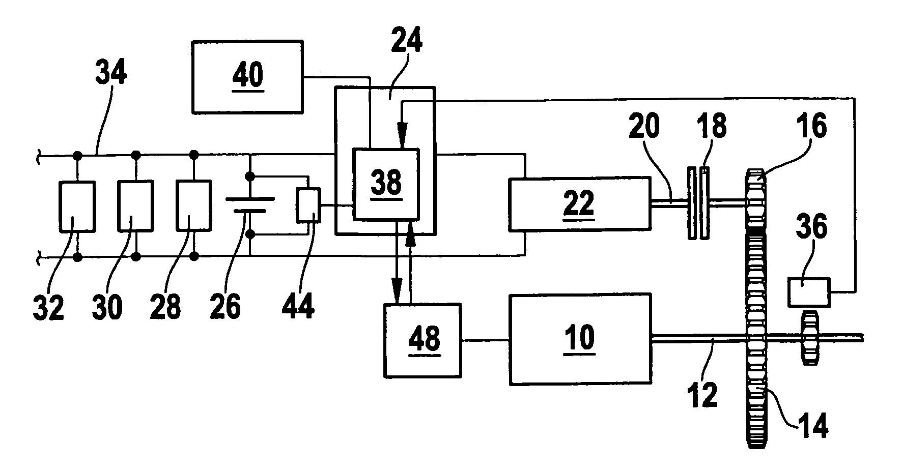
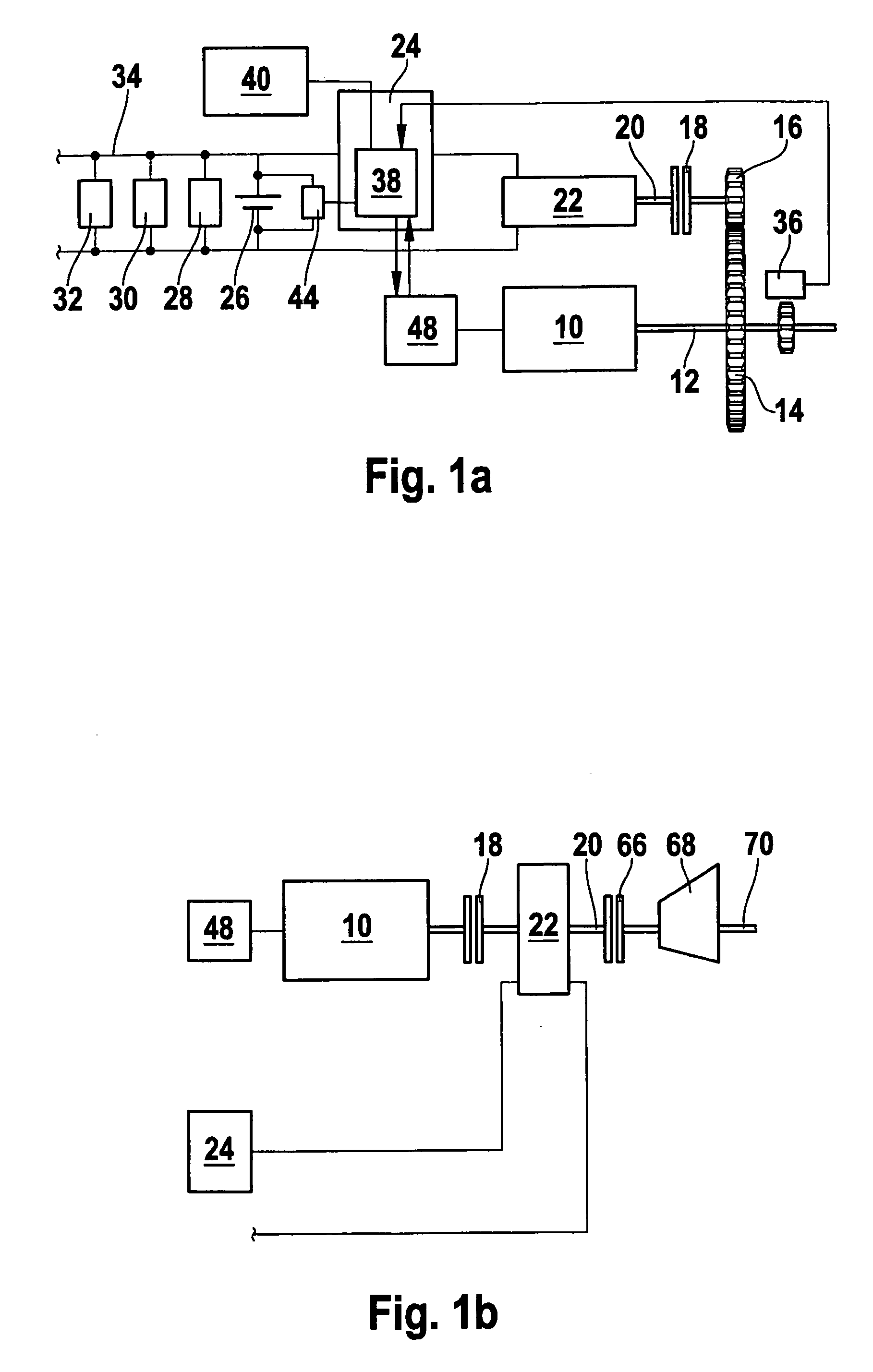
[0020]The hybrid drive of an exemplary motor vehicle, shown in FIG. 1a by way of example, as usual includes a combustion engine 10, whose crankshaft 12 is able to be coupled to driven shaft 20 of an electro machine 22 of the motor vehicle via two gear wheels 14, 16 and a clutch 18 acting as interrupting clutch, in particular. By way of example, FIG. 1b shows a hybrid drive for electric driving using combustion engine 10 decoupled from electro machine 22, i.e., with an open clutch 18. The output for the remaining drive train (starting clutch 66, gearing 68, drive wheels) takes place at driven shaft 20 of electro machine 22.

[0021]Electro machine 22 has a control unit 24 and is connected via this control unit 24 to a battery 26 of the motor vehicle, which supplies direct current to a multitude of loads 28, 30, 32 etc. in a vehicle electrical system 34. Loads 28, 30, 32 may encompass all power units of the motor vehicle that are operated by current, such as the rear-window defroster, th...


PUM


Abstract

A method for operating a motor vehicle having a hybrid drive, including a combustion engine having an engine management and at least one electro machine having a control unit, which is at least intermittently operated in an rpm-regulated manner and which is able to be in operative connection with a drive shaft of the combustion engine. For the closed-loop speed control of the electro machine, its torque is influenced by its rotational speed or a signal derived therefrom.

Description

FIELD OF THE INVENTION[0001]The present invention is based on a method for operating a hybrid drive, and on a motor vehicle having a hybrid drive.BACKGROUND INFORMATION[0002]Motor vehicles having a hybrid drive are discussed in the German patent document DE 10241018 A1, for example. Referred to as hybrid drives are drives in which at least one electro machine is provided in addition to a conventional internal combustion engine; depending on the design of a parallel hybrid drive, this electro machine can be coupled or is fixedly coupled to a drive shaft in the drive train of the motor vehicle and can operate both as generator or as motor. In generator operation, the electro machine is driven by the internal combustion engine and is thus able to generate electric current to supply electric loads of the motor vehicle. In motor operation, current is supplied from the vehicle battery in order to convert this current into driving energy for the motor vehicle or into starter energy for the...

Claims


Application Information

Patent Timeline
IPC IPC(8): B60W20/00B60K6/48
CPCB60K6/48B60W10/06Y02T10/6286B60W20/102Y02T10/6221B60W10/08B60L2240/12B60L2240/421B60L2240/423B60W2050/001B60W20/11Y02T10/62Y02T10/64
Inventor DEUBLE, PETERFALKENSTEIN, JENS-WERNERSTAHL, MANFRED
Owner ROBERT BOSCH GMBH
Learn More