Device for changing an operational status of a shifting element with two shifting element halves

a technology of shifting element and operating condition, which is applied in the direction of magnetically actuated clutches, mechanical actuators, mechanical apparatus, etc., can solve the problems of increasing the fuel consumption of the vehicle, undesirable permanent current flow, and shifting element over its operating life, so as to achieve low cost, low cost, and efficient operation

Inactive Publication Date: 2012-10-11
ZF FRIEDRICHSHAFEN AG
View PDF2 Cites 2 Cited by
  • Summary
  • Abstract
  • Description
  • Claims
  • Application Information

AI Technical Summary

Benefits of technology

[0018]Accordingly, the purpose of the present invention is to provide a mechanism for changing the operating condition of a shifting element having two shifting element halves, which can be highly, efficiently operated with little control and regulation effort and which takes up little fitting space.

Problems solved by technology

In addition, for the design of the drive machine and the drive converter unit combined therewith, the wear of a shifting element that takes place over its operating life is also taken into account since enlargement of the air gap caused by wear increases the control path.
However, such a permanent current flow is undesirable since on the one hand it imposes a load on the electrical and electronic components, and on the other hand it increases the fuel consumption of the vehicle.
Disadvantageously, due to the low tooth efficiency in the area of a gear system designed to be self-locking, actuating systems with self-locking require a higher torque from the drive machine over the full operating range of a shifting element than do the actuating systems without self-locking.
However, higher actuating forces can only be provided with drive machines of corresponding power.
To produce a self-locking actuation system that occupies less fitting space, a transmission ratio between the drive machine and the shifting element can be correspondingly increased, but this compromises the control dynamics to a considerable extent.
However, the use of electromagnetic holding brakes entails additional control and regulation complexity and requires corresponding hardware for actuating the electromagnetic brakes, thus increasing the manufacturing and development costs.
In addition, when there are frequent demands for changing the operating condition of the frictional shifting element to be actuated, then due to the system-inherent control dynamics of the electromagnetic holding brakes, the holding effect that they provide cannot be used to the desired extent, so the current needed for operating the electric motor cannot be reduced as much as desired.
In each of the known compensation devices, a compensation spring is functionally connected by additional lever elements to a rotary plate, but this entails structural complexity and actuating systems made with such compensation devices also occupy an undesirably larger amount of fitting space.

Method used


Image

  • Device for changing an operational status of a shifting element with two shifting element halves
  • Device for changing an operational status of a shifting element with two shifting element halves
  • Device for changing an operational status of a shifting element with two shifting element halves

Examples


Embodiment Construction

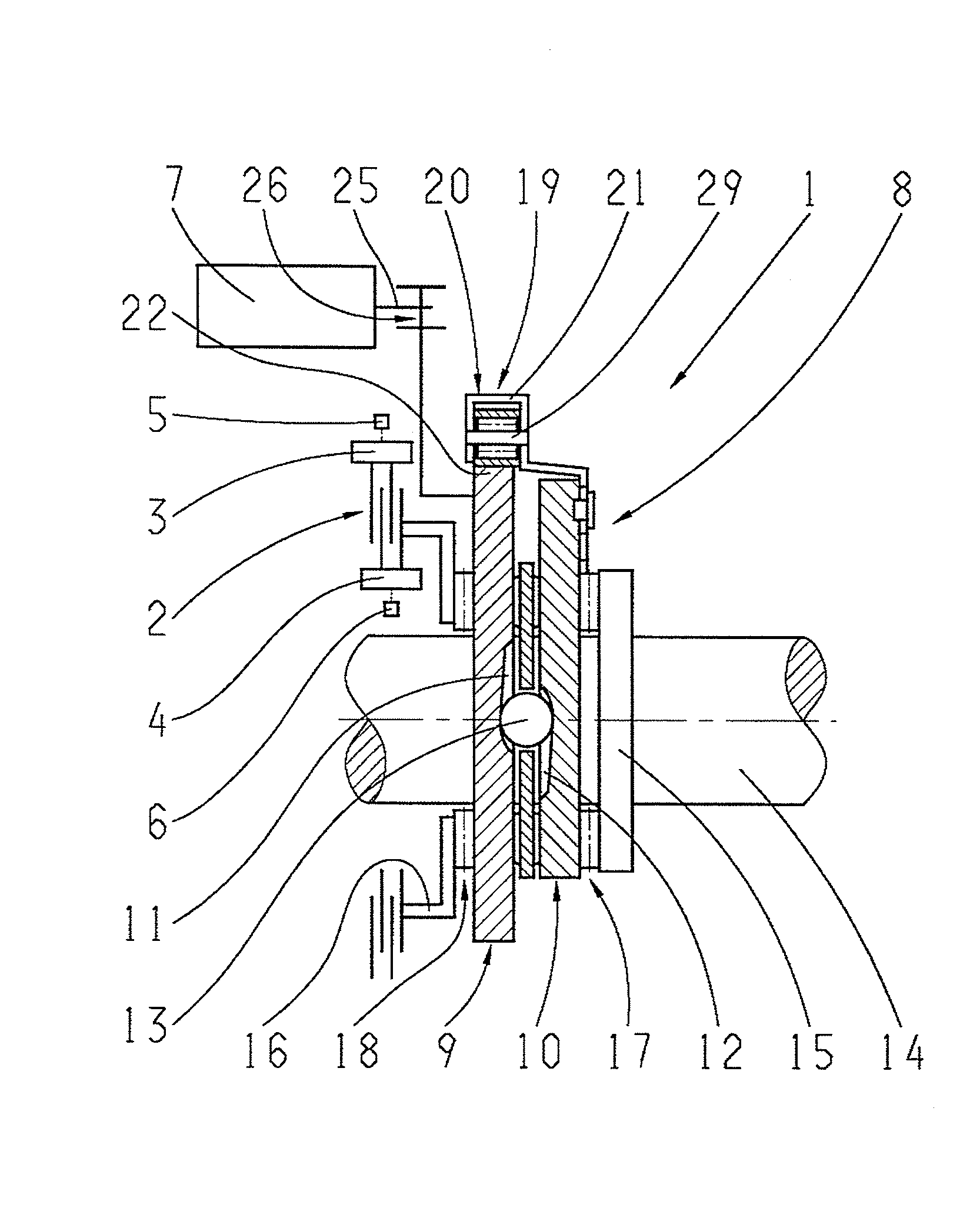
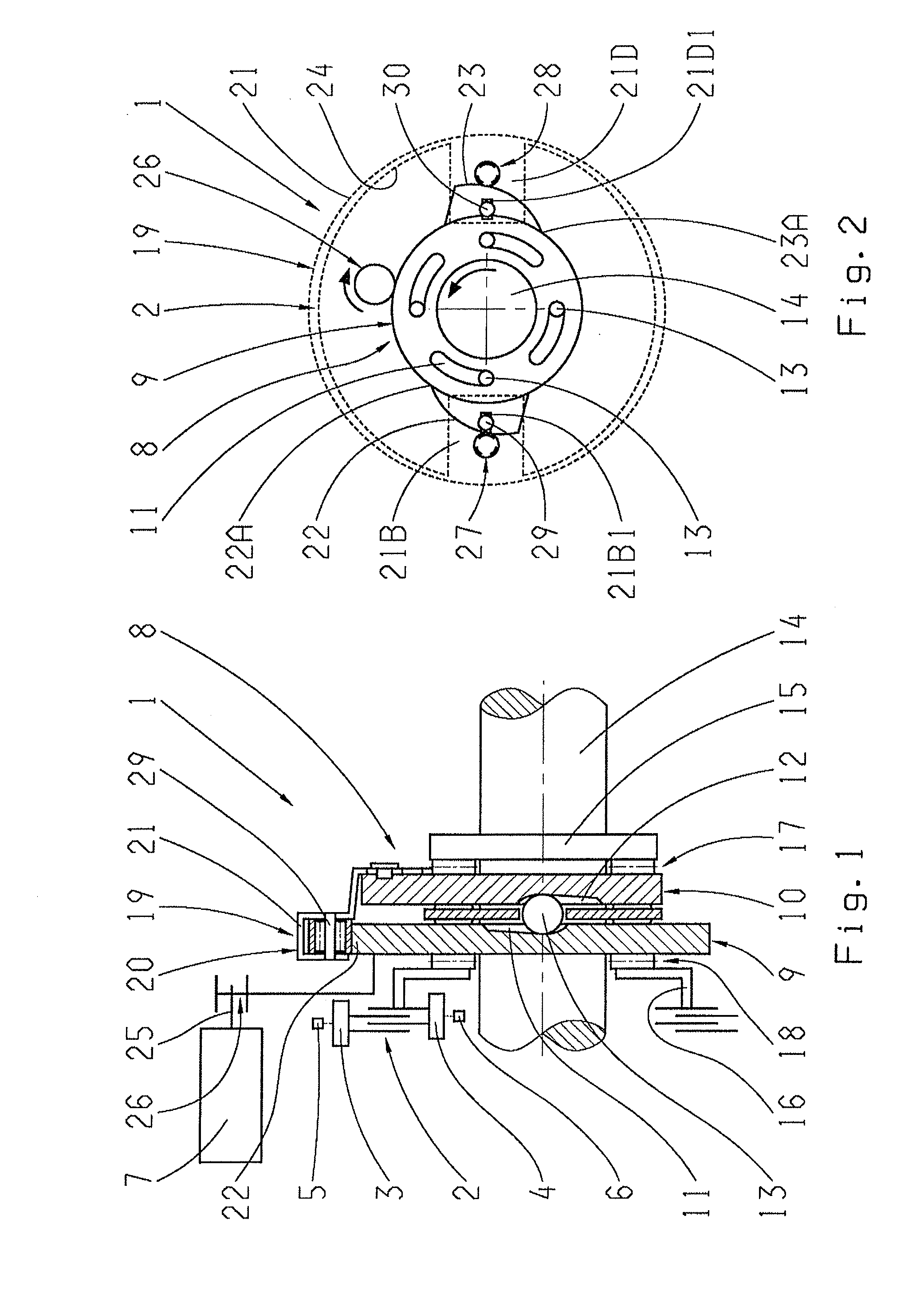
[0044]FIG. 1 shows a mechanism 1 for changing an operating condition of a shifting element 2, in this case in the form of a frictional clutch, or for actuating the shifting element 2. The shifting element 2 has two shifting element halves 3, 4 which can be functionally connected with one another in order to connect two components 5, 6 or which can be disengaged in order to break the connection between the components 5, 6. In the present case the shifting element 2 or disk clutch is an all-wheel distributor clutch of an all-wheel vehicle drive-train, by means of which, as a function of the transmission capability set in each case, a drive torque provided by a drive motor of the all-wheel distributor transmission can be distributed with varying degrees of distribution between two driven vehicle axles of the all-wheel drive-train. In the fully open operating condition of the shifting element 2, the drive torque of the drive motor is transmitted completely in the direction of one of the...


PUM


Abstract

A mechanism for changing the operating condition of a shifting element having two shifting element halves, which can either be functionally connected to connect two components or disengaged to break the connection between the components. The mechanism includes a drive machine and a drive converter unit in the area of which rotary drive motion of the drive machine can be converted into a translational actuation movement of the shifting element. A spring device is associated with the drive converter unit, whose spring force assists with actuating the shifting element in the engaging direction. The spring device includes an approximately circular flat spring element which, in at least one area of the drive converter unit, is in contact with at least one cam, whose stress condition varies as a function of an operating condition of the drive converter unit and is designed to be rotationally fixed.

Description

[0001]This application claims priority from German patent application serial no. 10 2011 006 965.8 filed Apr. 7, 2011.FIELD OF THE INVENTION[0002]The invention concerns a device for changing an operating condition of a shifting element with two shifting element halves.BACKGROUND OF THE INVENTION[0003]All-wheel vehicle drive-trains are increasingly made with frictional shifting elements by means of which, in each case, drive torque produced by an internal combustion engine, which is converted in the area of a transmission connected downstream from the internal combustion engine as a function of an overall gear ratio currently engaged in the transmission in an operating-condition-dependent manner, can be distributed in varying degrees between two driven vehicle axles of the all-wheel drive-train, in order to influence the driving behavior of the all-wheel vehicle, for example to increase the driving safety.[0004]To do this, the transmission capability of such shifting elements has to ...

Claims


Application Information

Patent Timeline
Patent Type & Authority Applications(United States)
IPC IPC(8): F16D13/08F16H63/44F16H63/30
CPCF16D27/004F16D28/00F16H2063/3056F16H63/3043F16D2023/123
Inventor BAASCH, DETLEFMAIR, ULRICH
Owner ZF FRIEDRICHSHAFEN AG
Why Eureka
Try Eureka