
Method for controlling a gearbox brake

a gearbox and brake technology, applied in the direction of instruments, vehicle sub-unit features, gears, etc., can solve the problems affecting the control dynamics and regulation ability, and only compensating inadequately, so as to improve the control ability, control the effect of dynamics and regulation ability, and avoid the effect of affecting the quality of synchronization and upshift processes

Inactive Publication Date: 2012-12-27
ZF FRIEDRICHSHAFEN AG
View PDF9 Cites 5 Cited by
  • Summary
  • Abstract
  • Description
  • Claims
  • Application Information

AI Technical Summary

Benefits of technology

[0014]Thus, the purpose of the present invention is to indicate a method for controlling a transmission brake of the type mentioned earlier in an automated change-speed transmission of countershaft design provided with claw clutches, by virtue of which the control properties of the magnetic pulse valves provided in this case are utilized and the duration of the synchronization processes are harmonized and their quality is improved, with relatively little expenditure.
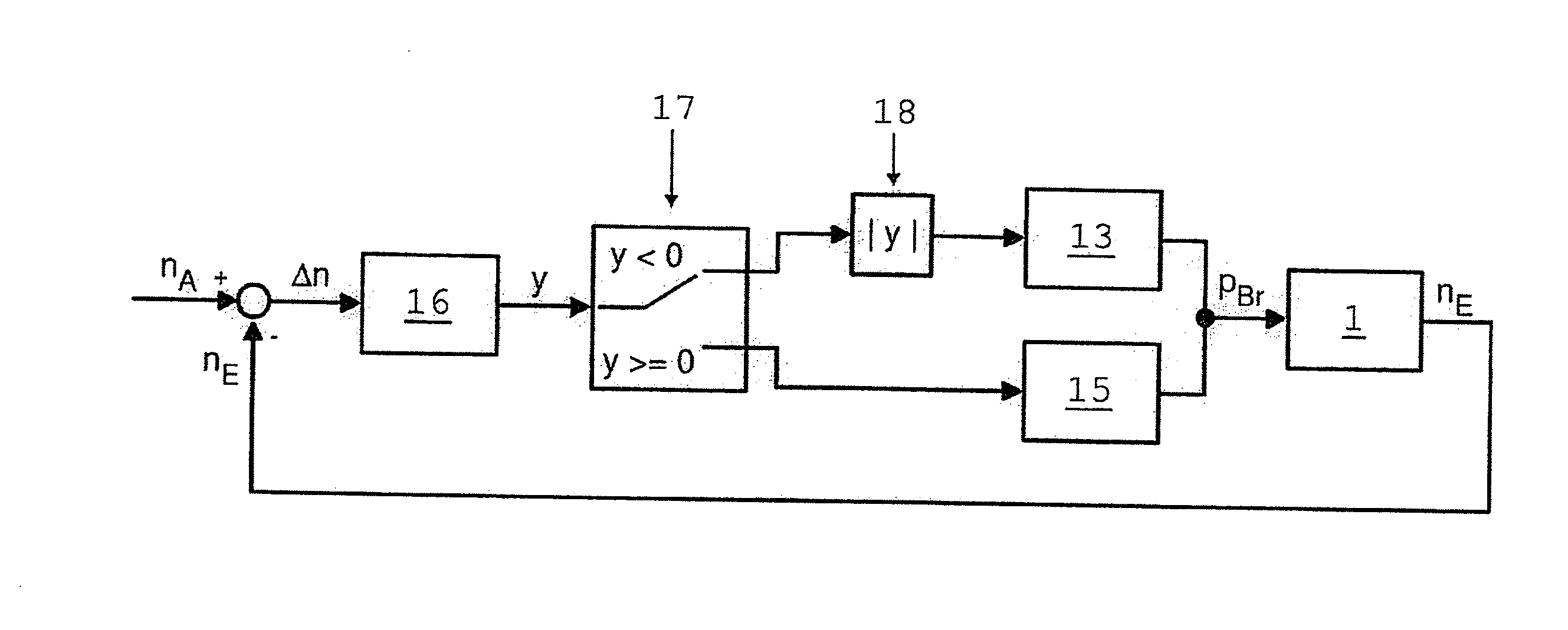
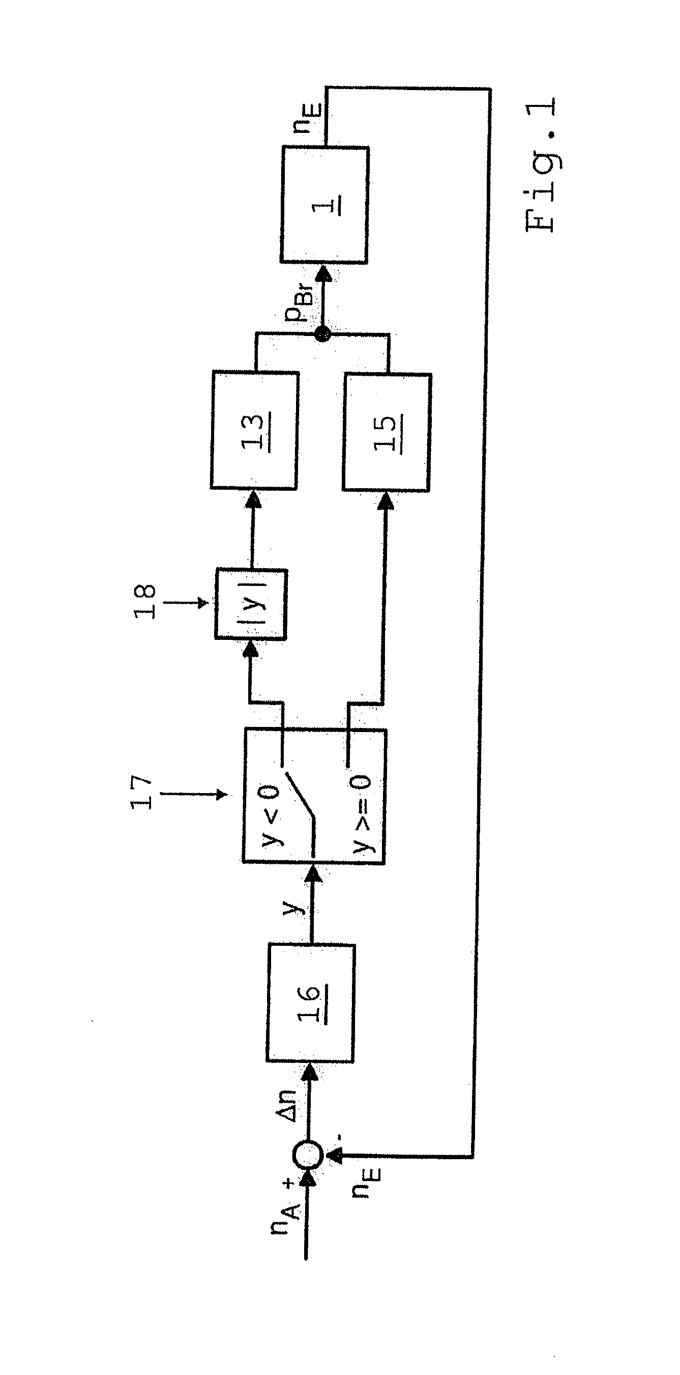
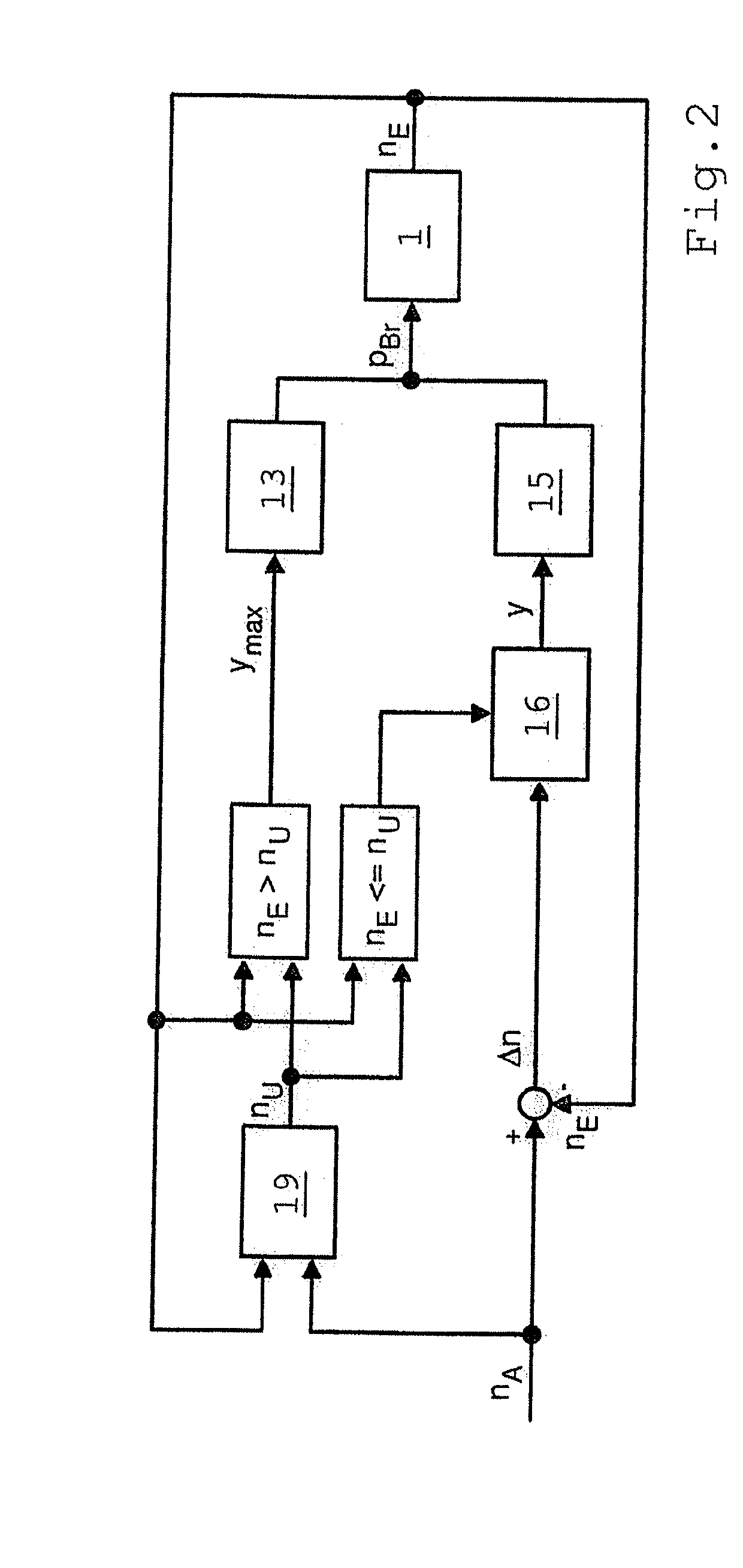
[0020]However, it is also possible for the inlet valve to be opened to its maximum extent until the shifting speed nU is reached. In this case the activation of the transmission brake and the braking of the input-side transmission shaft until the shifting speed is reached take place with the maximum control pressure pBr, but then disturbances such as pressure fluctuations in the pressure line and changed disk friction coefficients remain uncompensated at first and can result in varying durations of the engagement and braking phases. However, advantages compared with a regulated engagement and braking phase of the transmission brake are: quicker slowing down of the input-side transmission shaft and the smaller control expenditure.
[0025]For that reason the inlet and outlet valves are preferably operated with pulse frequency modulation (PFM). In this case the effective degree of opening of the pulse valve concerned and hence the control pressure in the pressure chamber of the brake cylinder is adjusted by varying the pulse cycle TZ with a constant pulse width TP. During this, at the end of every pulse cycle and having regard to a maximum valve dynamic, the magnet armature of the pulse valve always reaches the end position that corresponds to the closed rest position, which results in higher control dynamics and improved regulation ability.

Problems solved by technology

However, since particularly with an arrangement of the loose wheels in alternating pairs on the countershaft and the output shaft it would be relatively complicated to convert the speeds in each case to the relevant transmission shaft with the gear clutch of the target gear concerned, it is usual to relate both speeds, in each case regardless of the arrangement of the loose wheel concerned, uniformly to the same transmission shaft, preferably the input shaft.
Interfering factors such as operating temperature differences and varying friction coefficients of the disks are not directly detected in this type of control system, but are taken into account only indirectly by way of the speed gradients of the input speed, and are therefore compensated only inadequately.
In the aforesaid control sequences, interfering factors that occur in practice, such as pressure fluctuations in the pressure line of the pressure supply system, altered operating temperature and changed friction coefficients of the disks of the transmission brake, are compensated either by virtue of higher expenditure and complexity, for example by means of an upstream pressure regulation valve, or by a shift-quality-dependent correction of the lead time, or even not at all, which results in varying synchronization and upshift durations and in quality fluctuations of the synchronization and upshift processes.

Method used


Image

  • Method for controlling a gearbox brake
  • Method for controlling a gearbox brake
  • Method for controlling a gearbox brake

Examples


Embodiment Construction

[0033]FIG. 6 shows a typical transmission brake 1 of an automated change-speed transmission of countershaft design provided with claw clutches, with which the control method according to the invention can be used. The transmission brake 1 is in the form of a hydraulically or pneumatically actuated disk brake and is in this case arranged at the engine-side end of a countershaft 2 of the transmission (no more of which is shown). The inner and outer disks 3, 4 of the transmission brake 1 are connected in a rotationally fixed manner, in alternation to the countershaft 2 and to a brake housing 6 mounted on an end wall 5 of the transmission housing 5 on the engine side.

[0034]The transmission brake 1 is actuated by a piston 8 which is arranged to move axially in a brake cylinder 7 and is acted upon axially on the outside by the controllable control pressure pBr in the pressure chamber 9 of the brake cylinder 7, by which it is pushed toward the disks 3, 4 in opposition to the restoring forc...


PUM


Abstract

A method of controlling a transmission brake of an automated manual transmission of countershaft design provided with claw clutches where the transmission brake is functionally connected, on the input side, with a transmission shaft and which can be actuated hydraulically or pneumatically by inlet and outlet valves, each being a 2 / 2-way magnetic pulse valve. When upshifting under load to a target gear, after the gear under load is disengaged, to synchronize the target gear, the inlet and outlet valve are controlled in such manner that, at the end of the disengagement process, the input speed reaches a predetermined synchronous speed. The magnetic pulse valves are controlled such that the duration of the synchronization process is harmonized and its quality is improved and at least the outlet valve is opened, in a controlled manner, as a function of the rotational speed difference between the transmission input and output speeds.

Description

[0001]This application is a National Stage completion of PCT / EP2011 / 052087 filed Feb. 14, 2011, which claims priority from German patent application serial no. 10 2010 002 763.4 filed Mar. 11, 2010.FIELD OF THE INVENTION[0002]The invention concerns a method for controlling a gearbox brake of an automated change-speed transmission of countershaft design and which is provided with claw clutches, the brake being functionally connected to an input-side transmission shaft and being actuated hydraulically or pneumatically by means of an inlet valve and an outlet valve, each in the form of a 2 / 2-way magnetic pulse valve, such that during an upshift from a gear under load to a target gear, when the load gear has been disengaged, to synchronize the target gear the inlet valve is first opened, and once a shifting speed has been reached the inlet valve is closed and, to disengage the transmission brake, the outlet valve is opened in such manner that at the end of the disengagement process the ...

Claims


Application Information

Patent Timeline
Patent Type & Authority Applications(United States)
IPC IPC(8): F16H59/46G06F17/00
CPCB60Y2400/406F16H59/40F16H59/42F16H59/46F16H61/682F16H2003/123F16H2061/0078F16H2061/0411F16H2061/0474F16H61/0403
Inventor ULBRICHT, MARKUS
Owner ZF FRIEDRICHSHAFEN AG
Learn More