Ultrasonic nebulizer and method for atomizing liquid

a technology of ultrasonic nebulizer and liquid, which is applied in the direction of liquid spraying apparatus, medical atomisers, spraying apparatus, etc., can solve the problem of relatively expensive titanium horn components

Inactive Publication Date: 2008-07-03
DELPHI TECH INC
View PDF50 Cites 43 Cited by
  • Summary
  • Abstract
  • Description
  • Claims
  • Application Information

AI Technical Summary

Benefits of technology

[0004]A nebulizer in accordance with an exemplary embodiment is provided. The nebulizer includes a housing having a first chamber and a second chamber. The first chamber is configured to hold a liquid therein. The second chamber is configured to receive the liquid from the first chamber. The second chamber is configured to form standing pressure waves therein when the liquid therein is vibrated. The nebulizer further includes a piezo-electric device disposed in the second chamber. The piezo-electric device is configured to vibrate the liquid in the second chamber such that standing pressure waves are formed in the second chamber. The nebulizer further includes a meshed screen disposed at a predetermined distance from the piezo-electric device at a high amplitude region of the standing pressure waves and within a focal region of the piezo-electric device such that liquid in the second reservoir is atomized as the liquid propagates through the meshed screen.
[0005]A method for atomizing a liquid in accordance with another exemplary embodiment is provided. The method includes directing liquid from a first chamber to a second chamber in a housing. The second chamber is configured to form standing pressure waves therein when the liquid therein is vibrated. The method further includes vibrating the liquid in the second chamber utilizing a piezo-electric device such that standing pressure waves are formed in the second chamber. The method further includes atomizing liquid in the second chamber as the liquid propagates through a meshed screen wherein the meshed screen is disposed a predetermined distance from the piezo-electric device at a high amplitude region of the standing pressure waves and within a focal region of the piezo-electric device.

Problems solved by technology

A disadvantage with the foregoing design is that the titanium horn is a relatively expensive component.

Method used


Image

  • Ultrasonic nebulizer and method for atomizing liquid
  • Ultrasonic nebulizer and method for atomizing liquid
  • Ultrasonic nebulizer and method for atomizing liquid

Examples


Embodiment Construction

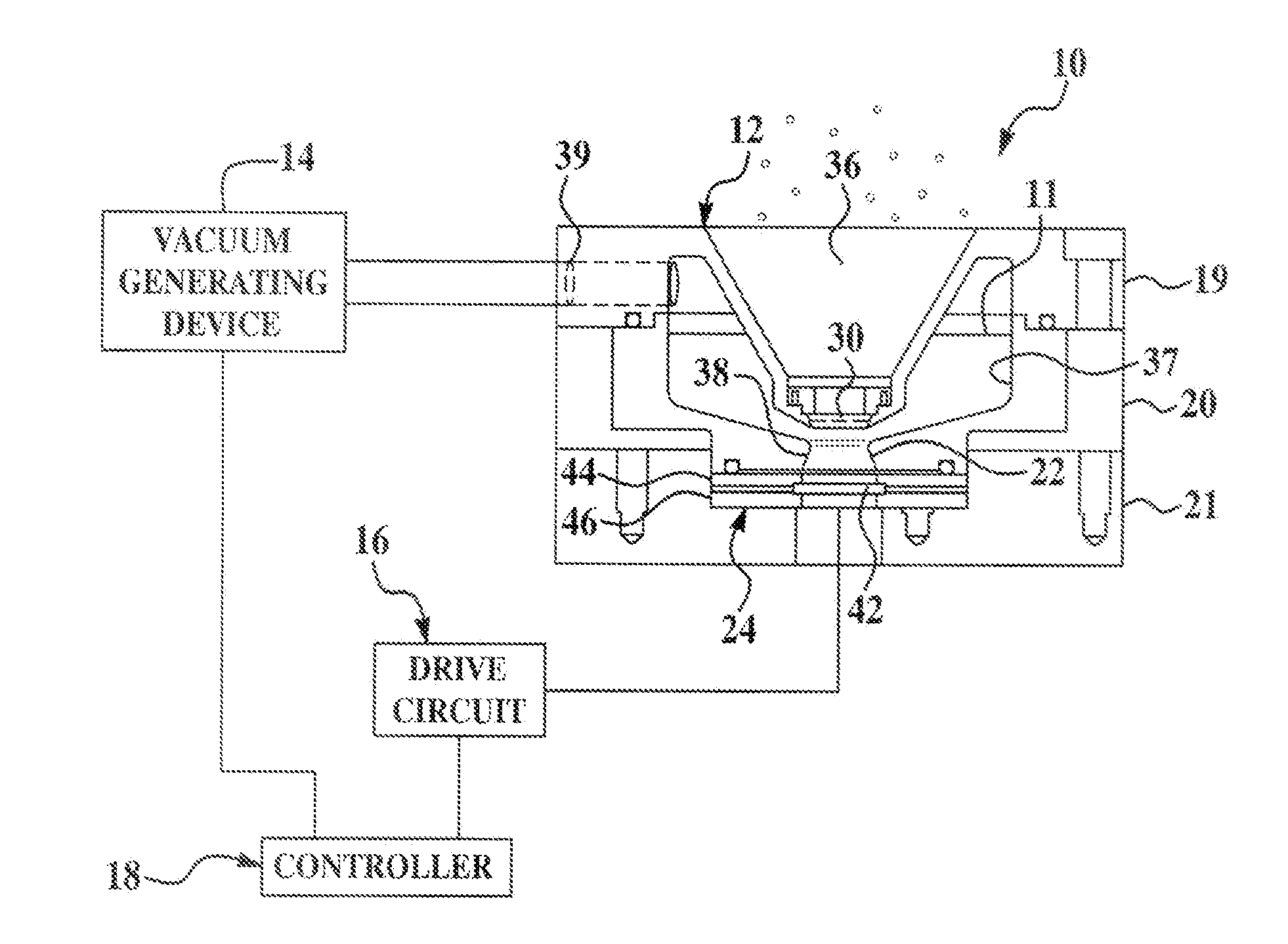
[0013]Referring to FIG. 1, a system 10 for atomizing a liquid 11 in a nebulizer 12 in accordance with an exemplary embodiment of the present invention is provided. The term “atomizing” as used herein means to reduce or to separate a liquid into tiny particles or into a fine spray. The system 10 comprises the nebulizer 12, a vacuum generating device 14, a drive circuit 16, and a controller 18.

[0014]The nebulizer 12 is provided for atomizing the liquid 11 into tiny particles. The nebulizer 12 includes a housing formed from plates 19, 20, and 21, a piezo-electric device 24, and a meshed screen 30.

[0015]The top plate 19 is coupled to a top surface of the plate 20. The bottom plate 21 is coupled to a bottom surface of the plate 20. The plates 19, 20, and 21 can be coupled together using any known fastening means, such as bolts for example. The plate 19 and the plate 20 define chambers 37 and 38 therein. The chambers 37 and 38 are provided for holding the liquid 11 therein. The chamber 38...


PUM


Abstract

A nebulizer and a method for atomizing liquid are provided. The method includes directing liquid from a first chamber to a second chamber in a housing. The second chamber is configured to form standing pressure waves therein when the liquid therein is vibrated. The method further includes vibrating the liquid in the second chamber utilizing a piezo-electric device such that standing pressure waves are formed in the second chamber. The method further includes atomizing liquid in the second chamber as the liquid propagates through a meshed screen wherein the meshed screen is disposed a predetermined distance from the piezo-electric device at a high amplitude region of the standing pressure waves and within a focal region of the piezo-electric device.

Description

BACKGROUND[0001]This application relates to an ultrasonic nebulizer and a method for atomizing a liquid.[0002]U.S. Pat. No. 6,670,034 describes a nebulizer that atomizes a liquid. The nebulizer utilizes a piezoelectric crystal that vibrates a titanium horn. The titanium horn amplifies the vibrations of the piezoelectric crystal and in turn vibrates liquid contacting the titanium horn such that the liquid is subsequently atomized. A disadvantage with the foregoing design is that the titanium horn is a relatively expensive component.[0003]Accordingly, the inventors herein have recognized that it would be advantageous to have a nebulizer that utilizes the liquid as the amplification medium instead of the titanium horn.SUMMARY OF THE INVENTION[0004]A nebulizer in accordance with an exemplary embodiment is provided. The nebulizer includes a housing having a first chamber and a second chamber. The first chamber is configured to hold a liquid therein. The second chamber is configured to re...

Claims


Application Information

Patent Timeline
Patent Type & Authority Applications(United States)
IPC IPC(8): A61M11/00
CPCA61M11/005
Inventor LOW, THOMASGARCIA, PABLOSHIMON, JEFFKOTNIK, PAUL T.ROSS, DAVID A.
Owner DELPHI TECH INC
Why Eureka
Try Eureka