Organic electroluminescent device

a technology of electroluminescent devices and organic materials, which is applied in the direction of luminescnet screens, vacuum obtaining/maintenance, discharge tubes, etc., can solve the problems of affecting the encapsulation of other elements, so as to effectively hinder the permeation of moisture and oxygen through the sidewalls

Active Publication Date: 2008-07-03
IND TECH RES INST
View PDF5 Cites 56 Cited by
  • Summary
  • Abstract
  • Description
  • Claims
  • Application Information

AI Technical Summary

Benefits of technology

[0007]The invention utilizes a structural design of a getter layer and a barrier layer to form an organic electroluminescent device (OLED), which can adsorb moisture and oxygen in the OLED and effectively hinder moisture and oxygen from permeating through the sidewalls of the OLED. Moreover, the invention is applicable for flexible OLEDs.

Problems solved by technology

However, this kind of self-luminescent element requires operating in an environment without moisture and oxygen to ensure prolonged operational life thereof.
However, the getter particles near the sidewalls of the substrate are rapidly saturated with moisture and oxygen.
However, the getters near the sidewalls of the encapsulant are also rapidly saturated with moisture and oxygen.
Furthermore, for a flexible organic electroluminescent, because the space of the device is not fixed, other elements are more likely to be damaged by the getters.

Method used


Image

  • Organic electroluminescent device
  • Organic electroluminescent device
  • Organic electroluminescent device

Examples


embodiment 1

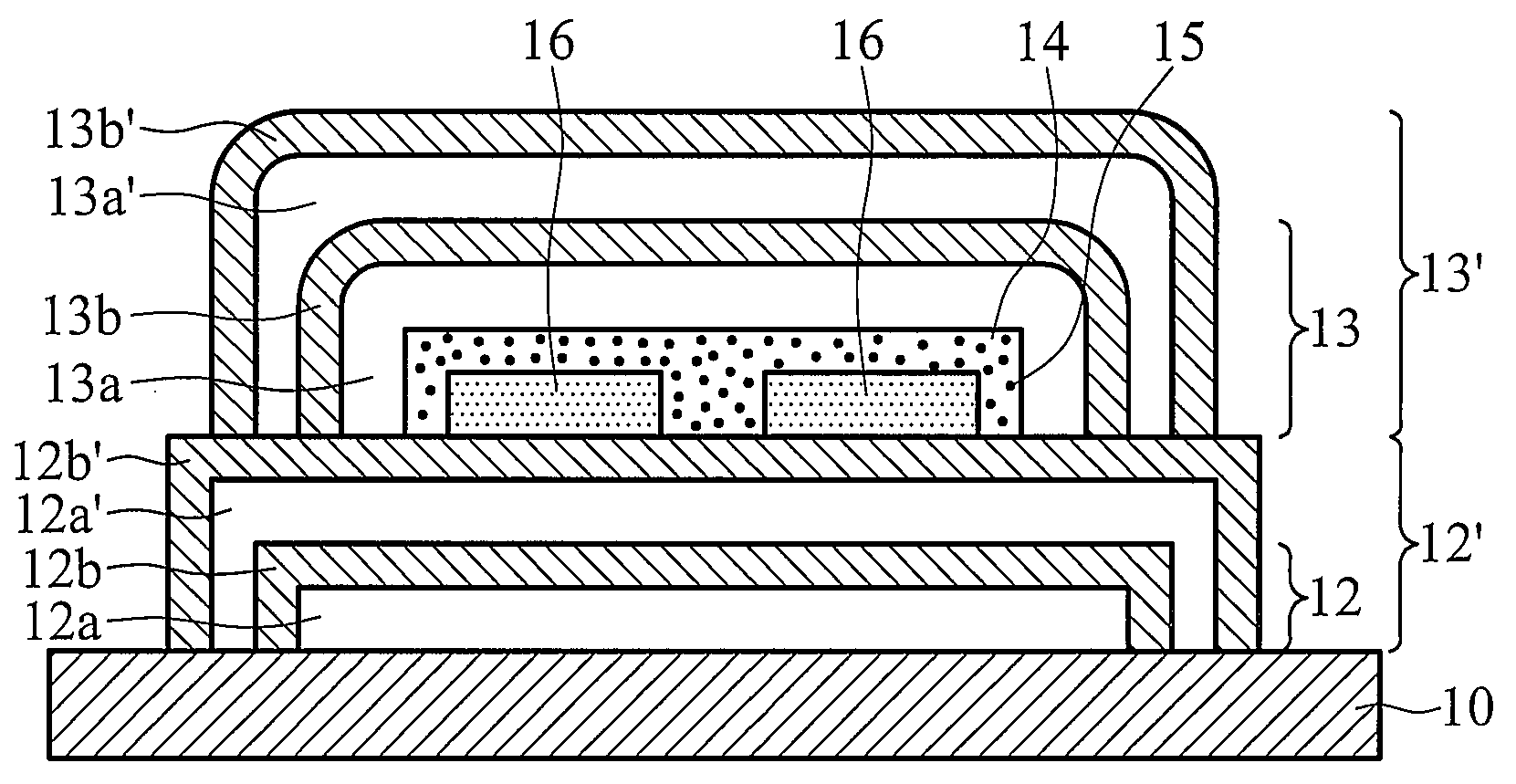
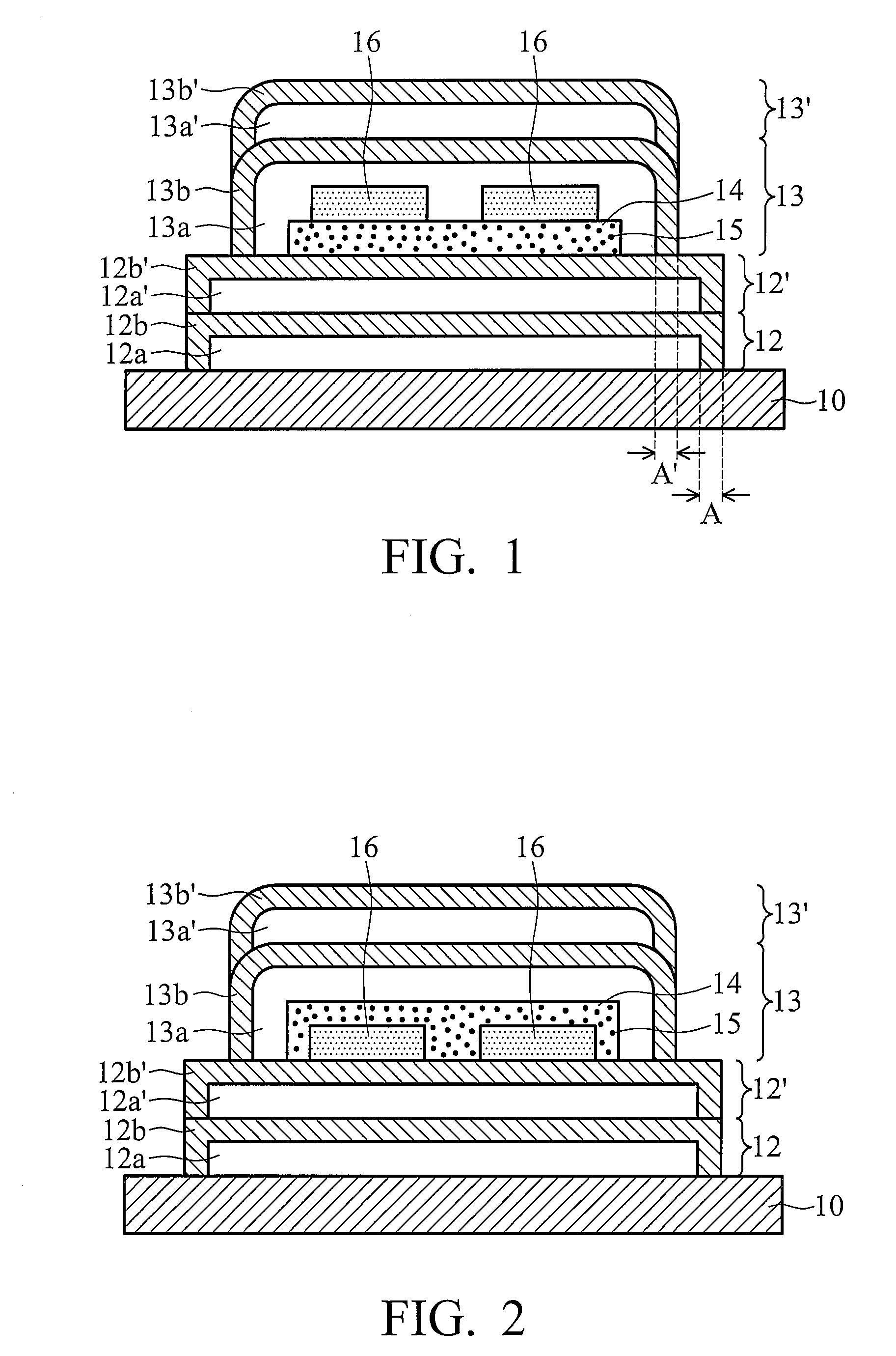
[0020]In embodiment 1 of the invention, the cross section of an organic electroluminescent device is shown as FIG. 1, wherein a getter layer 14 is disposed under an organic electroluminescent element 16. A substrate 10, such as plastic substrate or other flexible substrates, is first provided. Two barrier layers 12 and 12′ are formed on the substrate 10 by vacuum coating. FIG. 1 shows two barrier layers as an example, however one skilled in the art can readily appreciate that one or more than two barrier layers can be formed on the substrate.

[0021]First, an organic layer 12a is formed by vacuum vapor deposition, and then an inorganic layer 12b is formed by sputtering or chemical vapor deposition to completely cover the top and sidewall surfaces of the organic layer 12a forming the barrier layer 12. Next, an organic layer 12a′ and an inorganic layer 12b′ are formed on the above barrier layer 12 in sequence by the same method as barrier layer 12, to form a barrier layer 12′. The inorg...

embodiment 2

[0026]Referring to FIG. 2, it is a cross section of the organic electroluminescent device of the invention, wherein the getter layer 14 completely covers the top and sidewall surfaces of the organic electroluminescent element 16. The inorganic layers in the barrier layers of FIG. 2 are adjoined at the sidewalls of the barrier layers to hinder moisture and oxygen coming from passing through the sidewalls.

embodiment 5

[0027]Referring to FIG. 6, it is a cross section of the organic electroluminescent device of the invention. In addition to the getter layer 14 of FIG. 2, the organic electroluminescent device of FIG. 6 further comprises a getter layer 141 disposed between the organic electroluminescent element 16 and the barrier layer 12′. The getter layer 141 can adsorb the moisture and oxygen under the organic electroluminescent element 16. The composition and the coating method of the getter layer 141 can be the same as the forming of the getter layer 14.


PUM


Abstract

An organic electroluminescent device. The organic electroluminescent device comprises a first barrier layer disposed on a substrate; organic electroluminescent elements disposed over the first barrier layer and encapsulated with a second barrier layer; and a getter layer disposed between the first and second barrier layers. Each of the first and second barrier layers includes an organic layer and an inorganic layer covering the top and sidewall surfaces of the organic layer, thus providing stacked inorganic sidewalls to hinder moisture and oxygen.

Description

FIELD OF THE INVENTION[0001]The invention relates to an organic electroluminescent device, and more particularly to a flexible organic electroluminescent device providing sidewalls to hinder moisture and oxygen.DESCRIPTION OF THE RELATED ART[0002]An organic electroluminescent device (OLED) has advantages such as, a light weight, self-luminescence, low power consumption, no backlight requirement, no view angle limitation and a high response rate, thus, making it applicable for flat panel displays. However, this kind of self-luminescent element requires operating in an environment without moisture and oxygen to ensure prolonged operational life thereof.[0003]A conventional organic electroluminescent device has getters disposed in a space of a substrate for adsorbing moisture and oxygen. U.S. Pat. No. 6,465,953 discloses an organic electroluminescent device, which disperses a plurality of getter particles in the substrate to adsorb moisture and oxygen. However, the getter particles nea...

Claims


Application Information

Patent Timeline
Patent Type & Authority Applications(United States)
IPC IPC(8): H01L51/54H01J17/24
CPCB82Y20/00H01L2251/5369H01L51/5237B82Y30/00H10K50/846H10K50/8445H10K2102/331
Inventor LIAO, JUNG-YULIU, PEI-CHINGTSENG, MEI-RURNG
Owner IND TECH RES INST
Why Eureka
Try Eureka