Adaptive pole and zero and pole zero cancellation control low drop-out voltage regulator

a voltage regulator and adaptive pole technology, applied in the direction of electric variable regulation, process and machine control, instruments, etc., can solve the problems of pole-zero cancellation and unstable ldo regulator, and achieve the effect of reducing loop bandwidth, loop gain, and increasing loop bandwidth

Inactive Publication Date: 2008-07-03
IND TECH RES INST
View PDF3 Cites 67 Cited by
  • Summary
  • Abstract
  • Description
  • Claims
  • Application Information

AI Technical Summary

Benefits of technology

The present invention provides a method for compensating an LDO regulator that takes into account the non-dominant pole and changes with the load current. This results in a wider bandwidth and better phase margin, reducing jitter and improving the overall circuit performance. The method allows the LDO regulator to output stable voltage and avoid power supply noise.

Problems solved by technology

The technical problem addressed in this patent relates to improving the stability and performance of low drop out regulators in electronic circuits. Specifically, there is a risk for instability at lower loads due to poor phase margin caused by the interaction between different components within the circuit. This results in decreased efficiency and increased jitter, making it difficult to achieve optimal performance. The goal is to develop techniques to mitigate these issues and enhance the overall stability and dynamics of low drop out regulators.

Method used


Image

  • Adaptive pole and zero and pole zero cancellation control low drop-out voltage regulator
  • Adaptive pole and zero and pole zero cancellation control low drop-out voltage regulator
  • Adaptive pole and zero and pole zero cancellation control low drop-out voltage regulator

Examples


Embodiment Construction

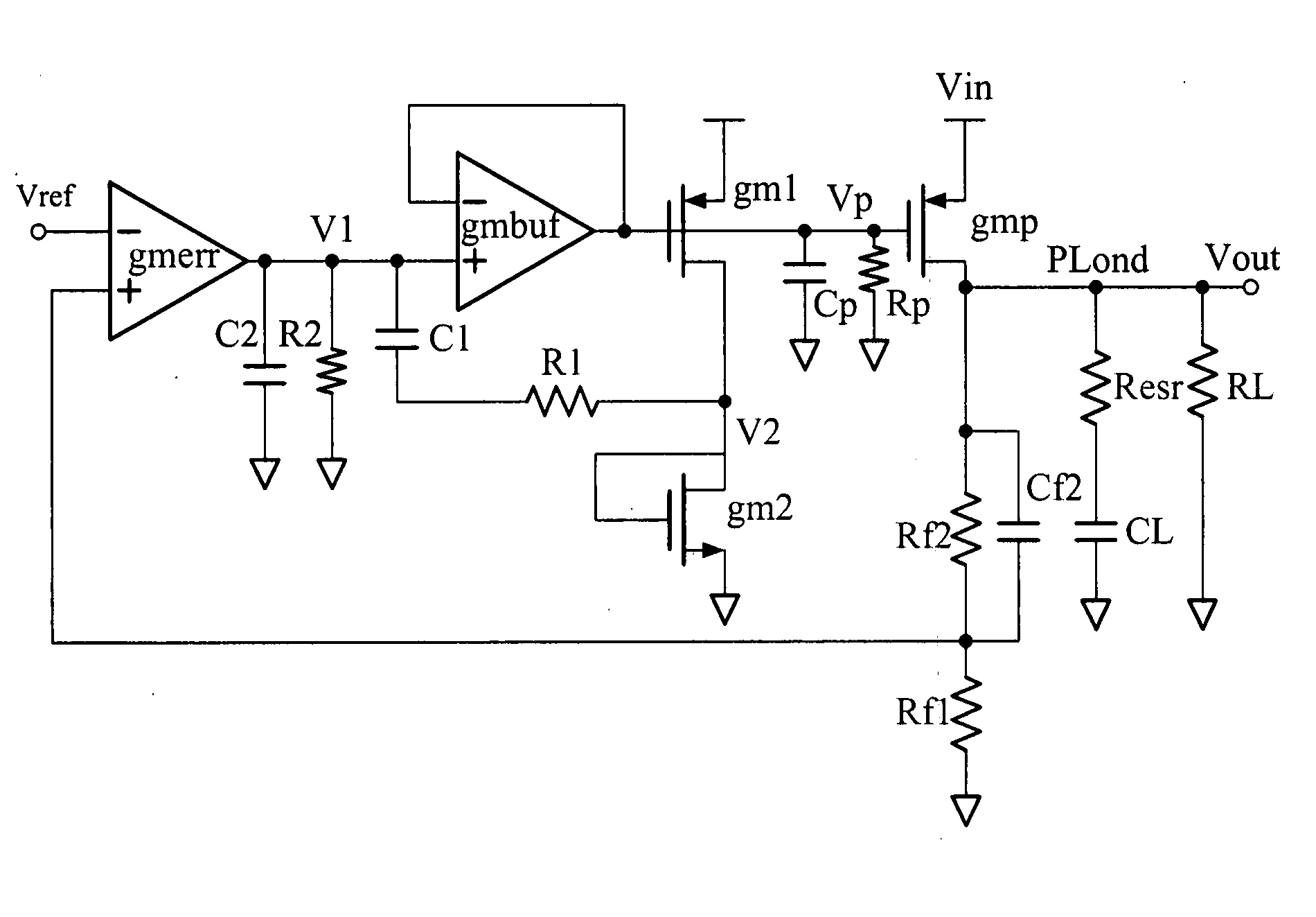
[0021]FIG. 5A is a block diagram of the LDO regulator used by the embodiment. The LDO regulator is an adaptive pole, zero, and pole-zero cancellation control LDO regulator. The LDO regulator includes a regulation unit 500, an error amplifier 510, a Miller Effect Pole control unit 520, a Pole-Zero Cancellation delay unit 530, and a feedback network 540. The pole and zero of LDO regulator of the embodiment can be adaptively adjusted with the change of the load, so that under all the load circumstances, the stability of the LDO regulator can be maintained in an ideal phase margin.

[0022]FIG. 5B is a circuit diagram of the LDO regulator used by the embodiment. The LDO regulator includes a regulation unit 500, an error amplifier 510, a Miller Effect Pole control unit 520, a Pole-Zero Cancellation delay unit 530, and a feedback network 540. The regulation unit 500 is a p-type metal oxide semiconductor (PMOS) or an n-type metal oxide semiconductor (NMOS). PMOS will be the preference. It inc...


PUM


Abstract

A adaptive pole and zero and Pole-Zero Cancellation Control Low Drop-Out (LDO) regulator is provided, which includes a regulation unit, an error amplifier, a Miller Effect Pole control unit, a Pole Zero Cancellation delay unit, and a feedback network. Pole and Zero could be adaptive regulated depend on various loads and maintain stably in a perfect phase margin.

Description


Claims


Application Information

Patent Timeline
Owner IND TECH RES INST
Why Eureka
Try Eureka