Low dropout regulator

a voltage regulator and low-load technology, applied in the direction of electric variable regulation, process and machine control, instruments, etc., can solve the problems of transient response oscillation in nature, the compensation strategy adopted in prior art 1 no longer holds good for the low-load-capacitor regulator suitable for soc applications, and the stability problem in actual scenarios, etc., to achieve good phase margin

Inactive Publication Date: 2007-07-12
ST ERICSSON SA
View PDF7 Cites 88 Cited by
  • Summary
  • Abstract
  • Description
  • Claims
  • Application Information

AI Technical Summary

Benefits of technology

[0056] It is an object of the present invention to provide a good phase margin for a low dropout voltage regulator (LDO) over no load to a certain maximum load current.
[0058] It is yet another object of the present invention to minimize the power consumption of the low-load-capacitor LDO.

Problems solved by technology

The fundamental design challenge in an LDO is to stabilize it over a zero load current (no load) to a maximum load current (full load) required for a particular application.
The most crucial drawback of prior art 1 arises from the fact that the LDO stability is critically dependent on an ESR value, which largely depends not only on a manufacturer of the capacitor, but also varies with an operating frequency and temperature and thus creates stability problem in actual scenarios.
So, the compensation strategy adopted in prior art 1 no longer holds good for the low-load-capacitor regulators suitable for the SoC applications.
This small phase margin makes the transient response oscillatory in nature and demands a long settling time.
Additionally, a smaller phase margin produces a bigger transient peak, which may cross a maximum voltage limit for the safe operation of the load circuits.
Although the phase margin may be slightly improved, the response becomes unstable as it is on the edge of a very sharply changing phase response.
This problem is removed for the LDO using a large external decoupling capacitor with bigger ESR, which limits the bandwidth of LDO to few MHz and ESR increases the damping of the LC tank circuit too.
Phase margin is degraded due to a sharp change in the phase from a complex pole pair and results in a damped oscillation in the transient settling response.
Unfortunately, as previously pointed out that lower the load capacitor value, larger is the voltage peak and trough during the quick transient load current change.
LDO required to have infinitely high bandwidth to respond to these instantaneous load current spikes which is not possible for a stable LDO.
When transient trough becomes less than the lower limit of controlled output voltage it may hamper the operation of the load circuitry temporarily, but if the transient voltage peak crosses the safe operating area (SOA) of load circuitry it can burst out the gates of the load circuits and may be responsible for permanent failure of the chip.
So, prior art 3 topology does not hold good in this low consumption mode operation when an LDO has to supply a small load current.
But this constant sink current is added to the consumption of the LDO 300, which is specifically needed to be consumed in the low load current region, which increases the consumption in the standby operation.
Although for low-load-capacitor LDO with negligible ESR and LDO having controlled output voltage near to reference voltage (for sub-100 nm low voltage CMOS circuits), one cannot utilize these two zeros efficiently for pole-zero cancellation and problem persists.
Additionally, designer has to meet stringent mathematical equalities, which may not be achievable in all process corners.
As already mentioned, this method of sinking a constant load current to achieve stability at no load is not a good low power solution.

Method used


Image

  • Low dropout regulator
  • Low dropout regulator
  • Low dropout regulator

Examples


Embodiment Construction

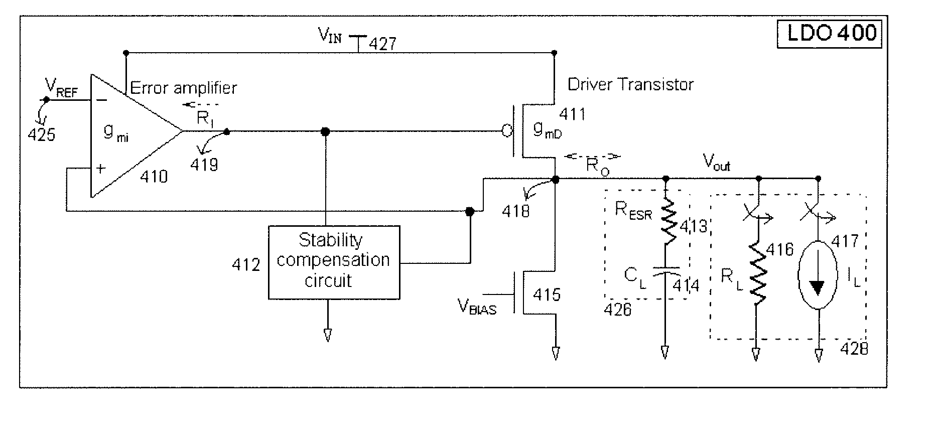
[0073] The present invention provides a stability compensation circuit for an LDO driving a load capacitor in a range of few nano-Farads to few hundreds of nano-Farads with a good phase margin over a no load to full load current range, and maintains minimum power area product for an LDO suitable for a SoC integration.

[0074]FIG. 4 describes a block diagram of an LDO 400 according to an embodiment of the present invention.

[0075]FIG. 5 shows a schematic diagram of an LDO (400) according to an embodiment of the present invention. The present LDO (400) can be considered as a two stage amplifier. The first stage 510, which is a differential to single ended differential amplifier, compares a reference voltage generated from a reference voltage generator circuit 530 with a regulated output voltage at node 524 of the LDO 400. The reference voltage and the regulated output voltage are connected to a negative and a positive terminal of an error amplifier 510 with respect to the output (node ...


PUM


Abstract

The present invention provides a low dropout (LDO) regulator with a stability compensation circuit. A “zero frequency” tracking as well as “non-dominant parasitic poles' frequency reshaping” are performed to achieve a good phase margin for the LDO by means of the compensation circuit. In this compensation method neither a large load capacitor nor its equivalent series resistance is needed to stabilize a regulator. LDO regulators, in system on chip application, having load capacitors in the range of few nano-Farads to few hundreds of nano-Farads can be efficiently compensated with this compensation method. A dominant pole for the regulator is realized at an internal node and the second pole at an output node of the regulator is tracked with a variable capacitor generated zero over a range of load current to cancel the effect of each other. A third pole of the system is pushed out above the unity gain frequency of the open loop transfer function with the help of the frequency compensation circuit. The compensation technique is very effective in realizing a low power, low-load-capacitor LDO desirable for system on chip applications.

Description

RELATED APPLICATIONS [0001] The present application claims priority of India Patent Application No. 3532 / Del / 2005, first filed Dec. 30, 2005 as a provisional application, for which a complete specification was filed Aug. 10, 2006, said applications being incorporated herein in their entireties by this reference. FIELD OF THE INVENTION [0002] This invention relates to a field of voltage regulators, and more specifically to a stability compensation of low-load-capacitor, low power, low dropout voltage regulator (LDO) providing a good phase margin over no load to full load current range. BACKGROUND OF THE INVENTION [0003] The driving force behind the increasing demand of low dropout regulators (LDO) stems from the requirement of efficient power management in battery operated portable consumer products for their low power operations. The fundamental design challenge in an LDO is to stabilize it over a zero load current (no load) to a maximum load current (full load) required for a parti...

Claims


Application Information

Patent Timeline
Patent Type & Authority Applications(United States)
IPC IPC(8): G05F1/00
CPCG05F1/575
Inventor MANDAL, SAJAL KUMAR
Owner ST ERICSSON SA
Why Eureka
Try Eureka