Video chat apparatus and method

a video chat and video technology, applied in the field of video chat apparatus and method, can solve the problems of not being able to achieve the intended purpose of eye-gaze correction, difficult to put it into a practical use, and giving a viewer a sense of discomfor

Inactive Publication Date: 2008-07-03
KK TOSHIBA
View PDF6 Cites 30 Cited by
  • Summary
  • Abstract
  • Description
  • Claims
  • Application Information

AI Technical Summary

Benefits of technology

[0011]According to embodiments of the invention, since the positions of the viewpoints of the virtual cameras are changed according to the positions of th...

Problems solved by technology

Therefore, when a window on which the other party of the video chat is not displayed at the center of the display, eye-gaze correction, which is the intended purpose, is not achieved.
Since the position of the viewpoint of the virtual camera is limited to the center of the display, when an image from a given virtual viewpoint is generated using three-dimensional position of a scene, the image having a partly lost background is obtained, which gives a viewer a sense of discomfort.
Therefore, it is not easy to put it into a practical use.
As described above, the related art has a problem such that the position of the viewpoi...

Method used


Image

  • Video chat apparatus and method
  • Video chat apparatus and method
  • Video chat apparatus and method

Examples


first embodiment

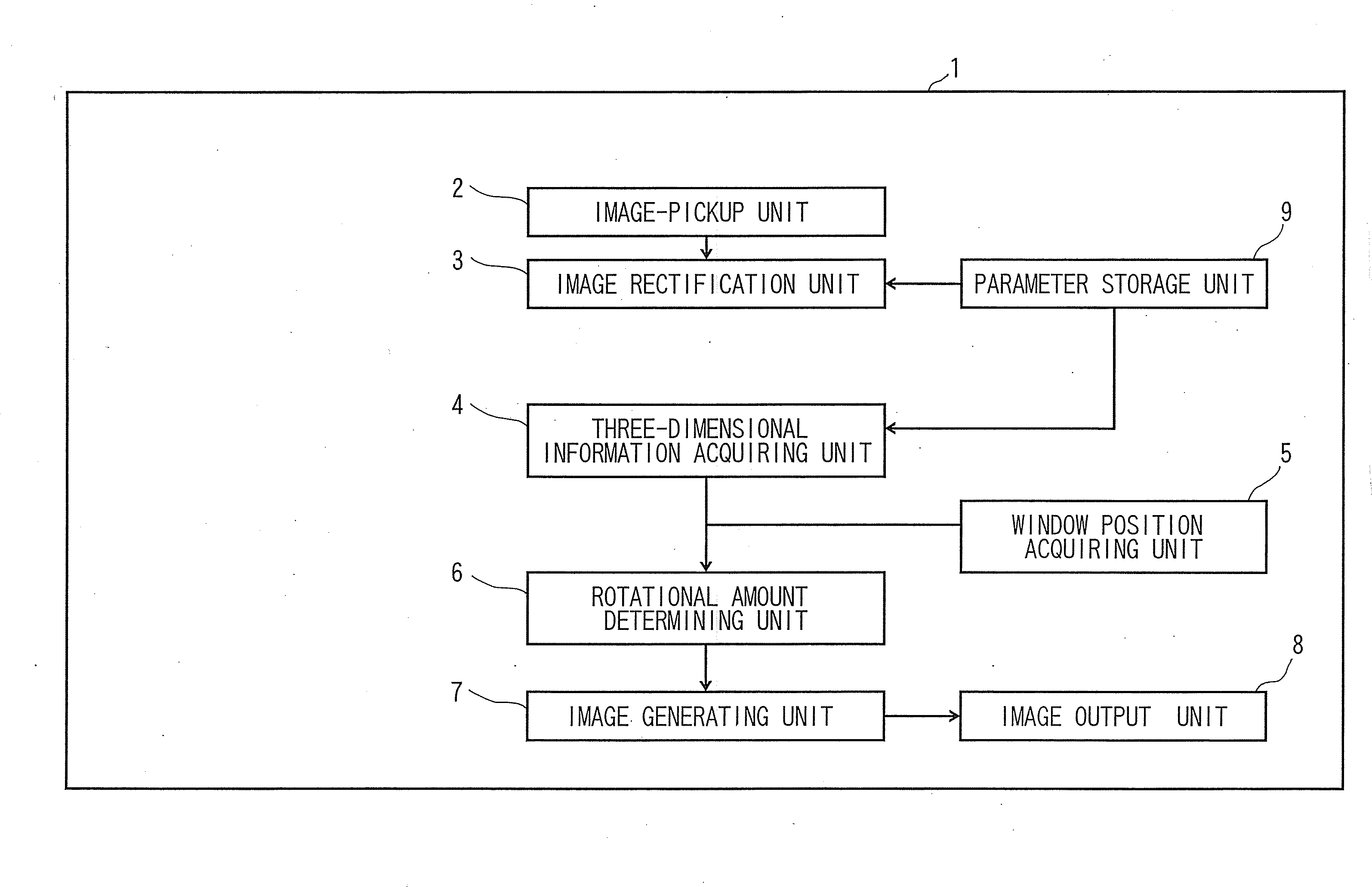
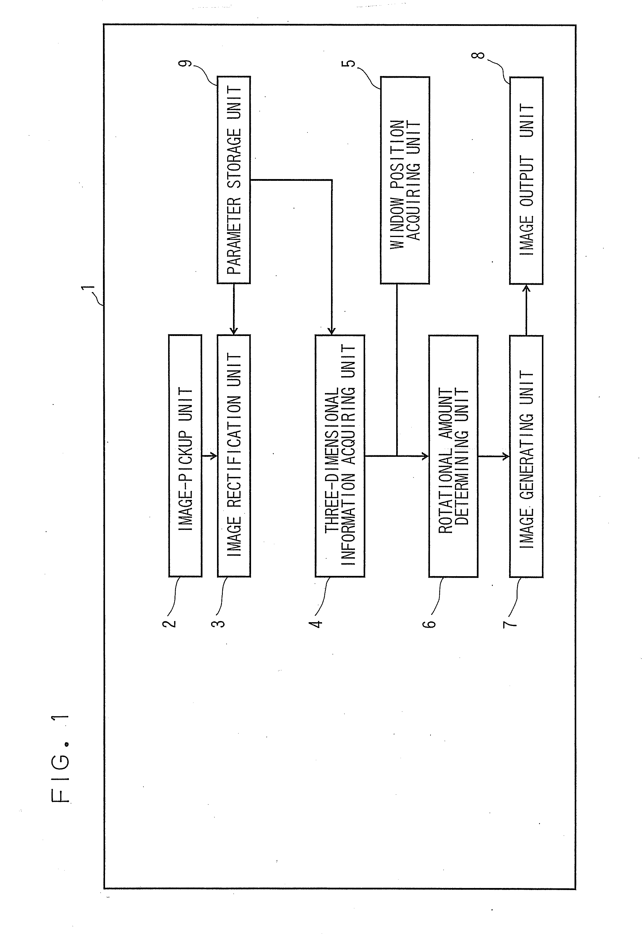
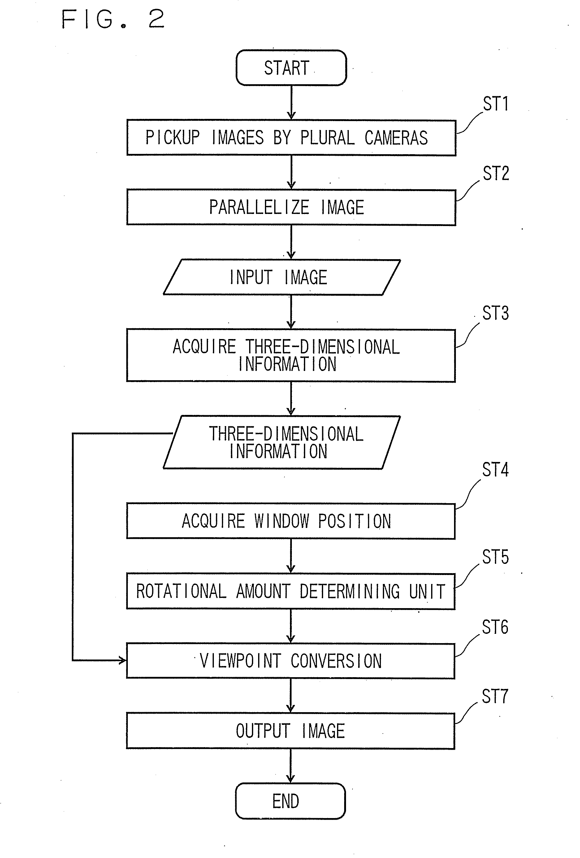
[0020]Referring now to FIGS. 1, 2, 5 and 6, a video chat apparatus 1 according to a first embodiment of the invention will be described.

[0021]As shown in FIG. 5, when four persons, A, B, C and D at different locations have a teleconference, each person has equipment including a laptop personal computer and two cameras attached to the laptop personal computer. It is assumed that three persons other than the owner of the laptop personal computer are displayed in three windows on a display of each laptop personal computer. The image of the face of each person is taken by the two cameras, and video signals taken by these cameras and voice signals taken by a microphone are transmitted through networks such as a LAN or internet.

[0022]In the related art, as shown in the drawing on the upper left side in FIG. 6, in the case of the laptop personal computer owned by Mr. A, for example, when Mr. A has a chat with Mr. B displayed on the upper left portion of the display (a user-gaze window in t...

second embodiment

[0054]Referring now to FIGS. 3, 4 and 7, a video chat apparatus 101 according to a second embodiment of the invention will be described.

[0055]In the video chat apparatus 101, only areas of foreground substances as subjects are detected from input images in a background difference processing unit 111 using background images recorded in a background image storage unit 110, and the three-dimensional position of the subject is acquired by a three-dimensional information acquiring unit 104. An image generating unit 107 restructures the images of the areas of the foreground substances from the virtual viewpoints and layers the same on the background images stored in the background image storage unit 110 to generate virtual viewpoint images, and sends the same to an image output unit 108.

(1) Configuration of Video chat apparatus 101

[0056]FIG. 3 is a block diagram showing the video chat apparatus 101 according to the second embodiment.

[0057]The video chat apparatus 101 includes an image-pic...

modification 1

(1) Modification 1

[0074]In the embodiments shown above, the center of rotation is determined to be the intersection between the normal line from the center of the display with respect to the display plane and the optical axis of the reference camera. However, an average of the depth values of the obtained three-dimensional position may be determined as the center of rotation.


PUM


Abstract

A video chat apparatus includes an image pickup unit having two cameras, a three-dimensional information acquiring unit, a window position acquiring unit, a rotational amount determining unit, an image generating unit, an image output unit, and a parameter storage unit. Eye-gaze correction is achieved only by changing the position of viewpoint of virtual cameras by the position of a window on the display and gazing at the other party of the chat.

Description

CROSS-REFERENCE TO RELATED APPLICATIONS[0001]This application is based upon and claims the benefit of priority from the prior Japanese Patent Application No. 2006-327468, filed on Dec. 4, 2006; the entire contents of which are incorporated herein by reference.BACKGROUND OF THE INVENTION[0002]1. Field of the Invention[0003]The present invention relates to video chat apparatus and method for teleconferences or the like, in which a virtual viewpoint is changed depending on the position of a window on which the other party of a chat is displayed, so that eye-gaze correction is achieved.[0004]2. Description of the Related Art[0005]In a system in the related art which is disclosed in JP Application kokai 2006-114023 and a non patent document, “Video-Teleconferencing System with Eye-gaze correction (U.S. Pat. No. 6,771,303 (Aug. 3, 2004) Zhengyou Zhang Microsoft Corporation)”, the position of the viewpoint of a virtual camera is set to the center of a display and an image is generated on t...

Claims


Application Information

Patent Timeline
IPC IPC(8): H04N7/14
CPCH04N7/144
Inventor SHIBATA, TOMOYUKIYAMAGUCHI, OSAMU
Owner KK TOSHIBA
Why Eureka
Try Eureka